Cutter Dredger Discharging Methods

A cutter dredger can deliver the dredged material in the following manner:


1. by discharge to reclamation ashore via combinations of floating pipeline, submerged pipeline
and shore pipeline;
2. by discharge into a hopper barge moored alongside the dredger (if so designed);
3. by crushing the material and leaving it on the seabed for subsequent removal by a trailer
dredger;
6. by “rainbowing” from the stern of the dredger;
7. by discharging through a spreader pontoon for accurate underwater placement.

The method adopted depends on the project work requirements

Mining methods

Digging deeper: Mining methods explained

  • Digging deeper: Mining methods explained

Share

Open-pit, underwater, and underground mining. These are the three main methods of mining we use to extract our products from the ground. In this Digging Deeper article, we take a look at these different methods and provide a glimpse into what each involves.

Mining is at the heart of our business at Anglo American. It is the foundation against which all of our activities rely and gravitate around. And that’s why it’s so important we conduct our types of mining activities effectively and intelligently.

Of course, before we break ground, we need to first discover mineral resources through exploration and allow a period for planning our mining techniques, ensuring all the right parts and pieces are in place and ready before we embark on mining activity.

Once all this is complete, we are ready to go.

But what are the mining methods we use to reach our diverse range of products?

1. Open-pit mining

Open-pit is one of the most common mining methods used and starts from the earth's surface, maintaining exposure to the surface throughout the extraction period. The excavation usually has stepped sides to ensure the safety of the miners and a wide ramp where equipment can travel, allowing the product to be removed efficiently from the site.

open-pit mining is practical when the ore-bodies of the rock are large and located closer to the surface.

Advantages of open-pit mining include:

  1. Powerful trucks and shovels can be used to move large volumes of rock.
  2. Equipment not restricted by the size of the opening you are working in.
  3. Faster production.
  4. Lower cost to mine means lower grades of ore are economic to mine.

The simple graphic below displays the sequence of events for the open-pit mining cycle.

2. Underground mining

Underground mining is used to extract ore from below the surface of the earth safely, economically and with as little waste as possible. The entry from the surface to an underground mine may be through a horizontal or vertical tunnel, known as an adit, shaft or decline.

Underground mining is practical when:

  1. The ore body is too deep to mine profitably by open pit.
  2. The grades or quality of the orebody are high enough to cover costs.
  3. Underground mining has a lower ground footprint than open pit mining.

What is underground mining?

The underground mining methods we use include room and pillar, narrow vein stoping and large-scale mechanised mining.

Room and pillar mining is a style of mining where tunnels are driven in a chess board pattern with massive square pillars between them which are gradually cut away as the work proceeds. We use this for mining coal.

Narrow vein stoping is performed in an underground excavation along geological ‘veins’ — distinct sheet-like bodies of crystallized minerals within a rock – where the mineral is mined and removed. To support underground mine stoping, we also have to make excavations for engine rooms and pump chambers or for access purposes such as shafts, drives, winzes and raises. We use this for mining platinum.

Large scale mechanised mining methods we use include:

  • long-wall mining, where a long wall of coal is mined in a single slice, usually by a large machine.
  • sub-level-caving, where levels of the ore are blasted by explosives; and
  • block caving, where large areas of the ore body are blasted and then extracted with the assistance of gravity.

We use these three different types of underground mining techniques for coal, diamonds and copper.

3. Underwater mining

Underwater mining is necessary when the product you’ve identified is located within an aquatic environment like the sea floor. It’s a unique challenge – and one that requires a responsible approach that thoughtfully considers the local ecosystem.

We conduct underwater mining with purpose-designed ships using either a remotely operated underwater vehicle or drill technology at depths of 100-140 metres below sea level.

The Four Main Methods of Mining

The Four Main Methods of Mining

December 4, 2019/in

Mining is the process of obtaining geological materials and valuable materials from the Earth. Materials that are acquired through mining are metals, gemstones, limestone, clay, gravel, and many more that cannot be grown through agricultural processes. These materials cannot be artificially created inside a factory or laboratory, which makes them obtainable through mining only.

There are four main methods of mining through which several different materials are acquired. Here we’ll take a look at these four methods and learn how each of them are carried out.

  1. Surface mining

Surface mining is a method of mining that involves removing the soil and the overlying rock on top of the mineral deposit. This method of mining gained popularity since the start of the 20th century, especially in North America where the majority of surface mining occurs. Most forms of surface mining use heavy equipment such as earthmovers to remove the overburden before bucket wheel excavators or dragline excavators extract the mineral.

Surface mining is done in five ways:

  • Strip mining – Strip mining is the most common surface mining method used to mine coal and lignite. The process is done by removing a strip of overburden before mining a seam of mineral. Strip mining is done only when the ore body is in close proximity to the surface.
  • Open-pit mining – Open-pit mining is the method in which minerals or rocks are extracted from the Earth via an open pit or borrow.
  • Mountaintop removal mining – Mountaintop removal mining (MTR) is done by mining coal seams underneath mountaintops. The mountaintop is removed by using explosives to break up layers of rock above the seam.
  • Dredging – Dredging is a method of surface mining that uses small dredges to suction up mined material from the bottom of a water body like oceans, lakes, and rivers.
  • Highwall mining – Highwall mining is done to recoup additional coal adjacent to a surface mined area. A continuous miner that’s remotely operated creates an entry into the coal seam and from there, the cut coal is transported by conveyors outside.
  1. Underground mining

Underground mining is a method of mining that extracts ore from underneath the earth’s surface. The entry from the earth’s surface to the underground mine may be created via a horizontal or vertical tunnel (also known as adit, shaft, and decline).

Underground mining is used when the ore body is too deep to be profitably mined by open pit, or when the quality of the ore body is high enough to cover up the expenses. Here are some of the most common ways underground mining is done:

  • Room and pillar mining – Tunnels are driven in a chess board-like pattern that are fitted with huge square pillars in between. This method of underground mining is commonly used to acquire coal.
  • Narrow vein stopping – A method of underground mining that is executed in an underground excavation along geological veins, which are crystallised minerals that appear in a distinct, sheet-like pattern. Narrow vein stopping is primarily used to mine platinum.
  • Block caving – The underground version of the open pit mining method where the ore body is undermined and allowed to collapse progressively under its own weight.
  1. Placer mining

Placer mining is a method of mining that uses water to recover precious metals from placer or alluvial deposits. Examples of deposits mined by placer mining are gold-bearing sands and gravel that has settled from rapidly moving streams to slower, more stable currents. Placer mining utilises the high density of gold to its advantage, causing it to sink at a much faster from moving water.

Panning is a form of placer mining that uses a pan where large amounts of water and a few handfuls of gold-bearing soil or gravel are placed. The contents of the pan are swirled together, causing the lighter material to be washed over the side and leave the gold and gravel behind. It’s one of the most ancient methods of extracting gold, and yet it’s still widely practiced today because of its low cost and simplicity.

Since the start of the 20th century, dredging became the most significant method of mining placer deposits, specifically bucket-ladder dredging which uses a continuous chain of rotating buckets around a ladder to scoop the material and deposit it through a barge.

  1. In-situ mining

In-situ mining (also called in-situ leaching or recovery) is a mining method that’s used to obtain minerals like uranium and copper through drilled boreholes into a deposit. In-situ mining works by dissolving naturally occurring minerals that are in a solid state. A leaching solution is pumped into the boreholes where it makes contact with the ore. The solution gets to work and dissolves the ore before being pumped back into the surface to undergo processing. This method of mining allows for the extraction of salts and metals from an ore body without resorting to conventional mining methods such as underground mining.

There are plenty of advantages to using in-situ mining. It’s the most environmentally way to mine ores, and involves minimal to no risk for both the workers and the communities surrounding the site. The reduced noise, dust, and greenhouse gas effects are what make in-situ mining an advantageous mining method, both in terms of its economic and environmental impacts.

The type of mining method used depends on a number of factors such as the type of mineral resource, the location of the minerals, and whether or not it’s justifiable to extract the mineral with expensive mining costs. Each mining method has its own advantages and varying levels of environmental impact, all of which are heavily considered prior to mining valuable minerals.

Should you require any further expert advise with regards to mining do not hesitate to get in touch

Waterfront Facility Inspection: Part I – Introduction

Waterfront Facility Inspection: Part I – Introduction

July 14, 2022

View the complete article here.

5-1 GENERAL CONSIDERATIONS

The fundamental purpose of any inspection is to provide the information necessary to assess the condition (capacity, safety, and rate of deterioration) of a structure. Waterfront structures to be inspected include: piers, pilings, wharves, quaywalls, fender systems, dolphins, and drydocks.

5-1.1 Inspection Objectives

Inspections are classified according to the objectives. These include:

  • Baseline – to obtain data on a facility that has not been inspected. This inspection involves the greatest “pre-inspection” effort.
  • Routine – to obtain data on general condition, confirm drawings, estimate repair costs, etc.
  • Design Survey – to obtain data for specifications or for detailed cost estimates.
  • Acceptance – to obtain data confirming that a repair has been completed according to plan or specification.
  • Research – to obtain data on deterioration rates, etc.

The usefulness of an inspection depends on establishing a clear and complete record. Although the level of inspection will determine the extent of information to be provided, in general the inspection will address the:

  • Identification and description of all major damage and deterioration of the facility.
  • Description of facilities inspected including updated layouts of pile plans (which occasionally differ significantly from the drawings available at the activity).
  • Documentation of types and extent of marine growth, if applicable.
  • Water depth, visibility, tidal range, and water current.
  • Assessment of general physical condition including projected load capacities.
  • Recommendations for required maintenance and repair (M&R).
  • Budgetary estimates of costs of this M&R, including examples of how estimates were derived.
  • Identification of any problems associated with mobilization ofequipment, personnel, and materials to accomplish repairs/maintenance.
  • Estimate of expected life of each facility.
  • Recommendations for types and frequencies of future underwater inspections.

5-1.2 Information an Inspection Should Provide

There are a number of reference documents dealing with waterfront inspections. The inspection procedures and planning factors outlined in this section have been taken from several of them. Two important references are:

  • NAVFAC MO-322, Inspection of Shore Facilities
  • NTRP 4-04.2.8, Conventional Underwater Construction and Repair Techniques
  • NTRP 4-04.2.9, Expedient Underwater Construction and Repair Techniques
  • NTRP 4-04.2.9, Expedient Underwater Construction and Repair Techniques

5-2 LEVELS OF INSPECTION

For any inspection objective, three levels of inspection effort are used for inspecting waterfront facilities:

5-2.1 Level I – General Visual Inspection

This inspection involves no cleaning of any structural elements and, therefore, is the most rapid of the three types of inspection. The purpose of the Level I inspection is to confirm as-built structural plans, provide initial input for an inspection strategy, and detect obvious major damage or deterioration due to overstress, impacts, severe corrosion, or extensive biological growth and attack.

5-2.2 Level II – Close-Up Visual Inspection

This inspection is directed toward detecting and identifying damaged or deteriorated areas that may be hidden by surface biofouling or deterioration and obtaining a limited amount of deterioration measurements. The data obtained should help estimate the facility’s load capability. Level II inspections will often require cleaning the structural elements. Since cleaning is time consuming, it is generally restricted to areas that are critical or which may be representative of the entire structure. The amount and thoroughness of cleaning to be done is governed by what is necessary to determine the general condition of the overall facility.

5-2.3 Level III – Highly Detailed Inspection

It is recommended that a “Level III” above and under water inspection be performed on piers identified for mooring use during heavy weather conditions. This inspection normally includes underwater inspections, and will often require the use of nondestructive testing (NDT) techniques. It may also require using partially destructive techniques, such as core sampling of concrete and wood structures, physical material sampling, or surface hardness testing. The purpose of this type of inspection is to detect hidden or interior damage, loss in cross-sectional area, and material homogeneity. A Level III examination will normally require cleaning. The use of NDT techniques are usually limited to key structural areas, areas that may be suspect, or structural members that may be representative of the underwater structure. Level III inspections require more experience and training than Level I or Level II inspections, and should be done by qualified engineering or nondestructive testing personnel. This type of inspection is covered in MO-104.2.

Inspection of waterfront facilities is considered to be a specialized control inspection within the Navy. The underwater inspection should be done by a qualified, certified diver supervised by an engineer or a qualified engineering diver. The structural assessment must be done by an engineer with experience and skill in inspection procedures and techniques.

منبع :

https://pilebuck.com/marine

Waterfront Facility Inspection

Waterfront Facility Inspection: Part III – Timber, Concrete, and Steel Structures

5-4 INSPECTION OF TIMBER STRUCTURES

5-4.1 Scoping the Problem

Timber damage is caused by:
• Fungal rot
• Marine borer and insect attack
• Shrinkage
• Overloading
• Connector Corrosion
• Abrasion
• Ice Lift

Waterfront deterioration and damage is found by walking the pier, by inspecting dolphins and below pier decks in a small boat or barge, and by underwater inspections.

When inspecting above the water, the inspector should take maximum advantage of low tide conditions in order to visually inspect the overall condition of the piling. This may determine that an underwater inspection is necessary. The underwater inspection should, on the other hand, take advantage of high water conditions in order to compile the most comprehensive field data on existing conditions.

5-4.2 Surface Inspections

Use Figure 5-10, “Timber Structures and Attachments (Above Water) Checklist” to ensure that a thorough inspection of all timber structures and their attachments above water is done. Include annual load testing of the pier decking if heavy equipment or vehicles are driven onto the pier. Sampling equipment and inspection data to be compiled are in Table 5-4.

The inspector should be alert, specifically in the areas of stringers, pile caps and top of piles, for signs of discoloration and softening of the wood, accompanied by a fluffy or cotton appearance. This may be an early sign of fungi damage. More advanced deterioration may take on the appearance of fruiting bodies, such as mushrooms. Further down the pile, the inspector should look for burrows or hollows in the wood, surface trenches in the outer layers of the pile, and loss of pile diameter. This may be evidence of marine borer attack.

5-4.3 Underwater Inspection

Use Figure 5-11 “Timber Structures and Attachments (Below Water) Checklist” to ensure that a thorough inspection of all timber structures and their attachments below water is done. An engineer should explain to the diver exactly what should be looked for: number and size of piles, type and depth of bulkheads, location of tiebacks, and cross bracing. The engineer shall evaluate the diver’s observations and determine the degree of hazard.

Additionally, when observing damage from marine borers (teredos) precautions need to be taken. As the diver swims up to the pile, he may be able to see the cilia, “waving,” as the worm filters food from the water, Otherwise, the worm feels the disturbance and withdraws the feeding hairs (and closes the opening). The diver is unable to see anything because the opening is:
• Small
• Closed
• Obscured by marine growth and shellfish

5-5 INSPECTION OF CONCRETE STRUCTURES

5-5.1 Scoping the Problem. Concrete damage appears in the following forms:
• Corroded rebar
• Alkali-silica reaction
• Freeze/thaw deterioration
• Abrasion wear
• Chemical deterioration from saltwater
• Overloading deterioration
• Shrinkage

These forms of damage are described in detail in Chapter 3. As with timber structures, concrete damage is found by walking the pier deck, inspecting below the pier deck in a small boat or barge, and underwater inspections.
The primary method of inspecting concrete is visual observation and sounding with a hammer. Only after problems are detected should other inspection methods be used. These other methods may include chipping away loose concrete to reveal the steel, coring, or Schmidt hammer.


5-5.2 Surface Inspections

Use Figure 5-12 “Concrete Structures and Attachments (Above Water) Checklist” to do a thorough inspection of all concrete structures and their attachments above water. Include annual load testing of the pier decking if heavy equipment or vehicles are to be driven onto the pier. Sampling equipment and inspection data to be compiled are given in Table 5-5.

Areas where the inspector should be particularly watchful for signs of deterioration, include:
• Inside corners and areas where radical changes occur in size of deck sections, curbs, and bollards.
• Construction joints.
• Poorly designed scuppers, drips, and curb slots, and other areas where inadequate drainage exists.
• Joints between the deck and pile cap, expansion joints where insufficient gap is allowed, and rigid joints between precast piles and cast-in-place pile caps.

The inspector should be alert for any change in appearance of the concrete surface and any change in the sound from the hammer:
• Erosion of the surface material or by cracking on the surface are signs of chemical attack.
• Erosion of surface material is a sign of freeze-thaw deterioration.

Use a hammer or gad (sharp pointed tool) to chip or probe the surface to detect the depth of deterioration.

Corrosion of the reinforcement can be detected from rust stains on the surface. More advanced stages of corrosion is indicated by cracks that run parallel to the steel reinforcing bars. At times, corrosion is hidden from view, but will be indicated by a hollow sound from the hammer. This can occur on heavily reinforced slabs, such as pier decks, where the reinforcement has corroded enough to delaminate a layer of concrete at the level of the reinforcing mat.

Give special attention to cracks found on the surface of a concrete structure. Make sketches that show the length and direction of the cracks. Overall cracking patterns and changes in crack length, width and direction with time are meaningful data to a structural engineer. Photographs are helpful, but only as a supplement to the sketches.

If there is evidence of significant deterioration, more detailed NDT techniques may be used in a scheduled Level III inspection. Refer to the Level III test procedures for concrete inspection for mechanical and electrical test methods in the Paragraph entitled, “Level III Test Procedures for Concrete Inspection.” The plan and sampling techniques shall be tailored to the specific areas of concern.

5-5.3 Underwater Inspection

Use Figure 5-15 “Concrete Structures and Attachments (Below Water) Checklist” to ensure that a thorough inspection of all concrete structures and their attachments below water is done. An engineer should explain to the diver exactly what should be looked for: number and size of piles, type and depth of bulkheads. The engineer will evaluate the diver’s observations and determine the degree of corrosion.

5-5.4 Level III Test Procedures for Concrete Inspection

If signs of deterioration or damage are found by Level I or II inspections then a Level III inspection, involving either nondestructive or destructive tests, may be required. Level III concrete inspections use mechanical and electrical test methods.

Mechanical and electrical test methods include:
• The Schmidt test hammer may be used in order to compare the relative surface quality of concrete at different locations on the same structure. The instrument measures the hardness of concrete surfaces by the extent of rebound of a spring-loaded steel plunger in a tubular frame. The relative surface quality of the concrete, which is also an indication of its compressive strength, can be obtained. Surface texture may reduce values obtained.
• Core samples are destructive in nature and should only be used if other techniques cannot satisfactorily define the damage. Core samples may be taken from selected areas in order to determine the cause and depth of deterioration, chloride, ion contamination for petrographic analyses, and the actual compressive strength. Take special care when setting up to drill a core, in order to avoid hitting steel reinforcement, especially prestressed steel. Steel reinforcement near the surface can be located by using a pachometer (rebar locator). The length of the core sample should be twice the diameter. After the core has been taken, patch the hole with non-shrink cementitious mortar.
• ASTM C876, Corrosion Potentials of Uncoated Reinforcing Steel in Concrete can be used to determine the extent of active corrosion and the degree of susceptibility of corrosion in other areas in the structure. Corrosion can be detected before visible signs appear. The method detects corrosion by measuring the electrical potential of the steel. An electrical connection is made from one side of a voltmeter to an embedded steel-reinforcing bar that has been exposed. The other side of the voltmeter is connected to a copper sulfate half-cell, which is then put in contact with the concrete surface at various locations. The magnitude and sign of the resulting voltage is an indication of corrosion activity.
• Ultrasonic methods are available to inspect concrete for voids that cannot be seen, such as honeycomb pockets, and for internal deterioration by cracking. Pulse velocities and fundamental frequencies are imposed in the concrete structure to search for imperfections. Sonic methods conducted at specific time intervals can monitor progressive deterioration. Interpretation of data is a highly specialized skill.

Before starting any of the above tests, a test plan must be prepared and the areas to be tested must be cleaned thoroughly.

5-6 INSPECTION OF STEEL STRUCTURES

5-6.1 Scoping the Problem

There are six major types of steel structure deterioration to watch for in the marine environment:
• Corrosion
• Abrasion
• Loosening of structural connections
• Fatigue
• Overloading
• Loss of foundation material

The causes and forms of steel deterioration are described in detail in Chapter 3.

5-6.2 Surface Inspections

Generally, visual inspections will detect most forms of deterioration of steel structures. Use Figure 5-16 “Inspection of Steel Structures (Above Water) Checklist” to ensure a thorough inspection of steel structures above water is done. In the event that more detailed NDT techniques are required under a Level III inspection, a plan and sampling techniques must be developed and tailored to the specific areas of concern.

Some types of corrosion, however, may not be detected by visual inspections. For example, inside steel pipe piling, anaerobic bacterial corrosion caused by sulfate-reducing bacteria (Figure 5-17) is difficult to detect by visual inspection. Fatigue distress can be recognized by a series of small hairline fractures perpendicular to the line of stress but these are difficult to locate by visual inspection. This type of problem, however, is more prevalent to offshore platforms with welded structural connections than to standard piers and wharves.

Cathodic protection systems need to be closely monitored both visually and electrically for signs of loss of anodes, wear of anodes, disconnected wires, damaged anode suspension systems, and low voltage.

5-6.3 Underwater Inspections

Use Figure 5-19 “Under Water Steel Structures Checklist” to ensure that a thorough inspection of underwater steel structures is done. An engineer should explain to the diver exactly what to look for: number and size of piles, type and depth of bulkheads. The engineer shall evaluate the diver’s observations and determine the degree of hazard.

منبع :

https://pilebuck.com/marine/

Marine Construction

Accessories for Marine Construction Barges

October 18, 2022

View the complete article here.

Since the earliest civilizations started to construct their cities on waterways, transporting goods and materials on water has proven to be the most efficient method of transportation.

Did you know that—according to American Waterways Operators— a typical inland barge has a capacity 15 times greater than one rail car? And 60 times greater than one semitrailer-truck? And one 15 barge-tow can move the equivalent of 216 rail cars or 1,050 semitrailer-trucks?

Needless to say, barges are an integral part of the marine industry—as well as our nation’s infrastructure. For that reason, we wanted to dedicate an entire article to the accessories that make this invaluable piece of equipment even more efficient.

What Type of Barge is Right for Your Project?

There are a wide variety of types and sizes of barges, and the one you need will depend on your project specs. Whether you own or lease or are still in the market, you’ll likely need to choose between coastal or inland barges, as well as deciding on a deck, spud, hopper, and shale barges—just to name a few.

As we mention in the Pile Buck Buyer’s Guide for Barges, we recommend the following suppliers for barges—McDonough Marine, Smith Bros, and Shugart Manufacturing. . Either of these companies will have the necessary inventory, and be able to help you select the ideal barge for each particular application as well.

What’s the difference between each barge type? Some differences are subtle, while others are significant. Since Pile Buck’s primary focus is marine construction, most of this article will look at the right accessories for spud and other related barges—as these are geared more towards building than transporting.

Inland barge. Photo credit: McDonough Marine

Safety and Stability: Barge Must-Haves

Regardless of the type, size, or project capacity of your barge, the need for adequate safety features should be obvious. Needless to say, ladders, rails, hatch covers, deck cleats, and other standard accessories have to be high quality and in solid, working condition. Depending on where your barge is operated, you could find yourself far from a supplier—dead in the water—while waiting for something as simple as a deck ladder to arrive.

When considering your ladders, think about the extra weight you’d add—possibly unevenly—by using a heavier material than you need. Most suppliers can outfit you with sturdy but lightweight aluminum ladders with a manageable tread size and distance. Railings tend to come in standard ten-foot sections, and most of them are available in heights up to 42-inches.

And, of course, barges require anchors of the appropriate build for the bulk of the vessel, and construction barges are no different. If anything, the nature of the barge and its payload makes the anchor even more of a consideration. The major distinction will likely be the type of marine bottom where you tend to operate. A fluke style anchor, for example, is best at sandy and muddy locations, while a flipper style is a more all-around condition anchor. Either way, you have to make sure that your anchor has enough HHP rating (high holding power) for the weight of both your barge and any cargo or equipment you’re carrying

The Importance of Spuds and Spudwells

Of course, for marine construction, you’ll probably be working off a sectional barge or a spud barge so you can dig into the sea floor, lake bottom, or riverbed—in order to stabilize yourself. These types of barges will be outfitted for mooring to the bottom while you’re working. The steel spuds will fit through the pocket-like spudwells that are anchored to the perimeter of the barge with a locking system. Even though these accessories are standard equipment for marine construction, it’s ultimately up to you to make sure your spuds and spudwells are of the top quality for both safety and ease of use.

It’s also crucial to consider the size and amount before you order spudwells and spuds. Depending on the size and location of your barge, two side-mounted or four of them positioned at the “corners” are the absolute minimum you’ll need in order to keep everything stable. If you’re use a barge-mounted crane (more on that below), you could need more. And remember that a supplier can help you determine the right width and length of both your spudwells and your spuds in order to make sure you’re properly outfitted.

Customer-built tandem winch package, consisting of two Pullmaster H50 winches and diesel powered HPU. Photo credit: F&M Mafco

Winches and Hoists for Barges

In order to complete serious projects, your barge will need to be outfitted with power equipment that will be sufficient enough to move building materials and supplies around. That’s where winches, hoists, and cranes come into play. Like any other winch, a barge winch will be pulling its load in a horizontal direction (nothing more than a 45-degree angle)—whether it’s across the deck, a dock, or even across the water. And it’s important to make sure your deck is reinforced for the weight of the winch, as well as the workload it’s going to pull.

When choosing a winch for your barge, you’ll also have to decide which kind of winch is appropriate for your needs. Two of the most significant factors in determining the specs will be the line material, as well as the lift capacity. Winches can have different types of line—chain rope or cable—depending on their purpose. You’ll also need to figure out if this is a standby piece of equipment (meaning it’s not getting frequent use) or if it’s going to get frequent light or heavy use. That will determine your positioning, which could need to be reinforced.

On that note, if your project requires a hoist or full-scale crane, the barge needs to—not only be able to withstand the weight of the crane and the attachments—but also the weight of the load. Make sure your deck and spuds are rated for the level of hoist you’ve got on board—standard, heavy, or severe use—as well as the type of power it requires. Having wooden crane mats underneath the crane on top of the deck surface will help distribute that weight across the width of the barge. The right spuds and spudwells around that area will also prevent avoidable disasters. Remember, your hoist may only be lifting, but a crane will require your barge to be able to withstand the shift in weight as the cargo is moved from side-to-side as well.

Handling the Barge Extras

Anything you intend to move on your barge, obviously, must be properly secured, but—that being said—the weight of the equipment has to be factored in. For example, if your hoist or crane will use concrete buckets or clamshell grapples, these add significant weight and must be balanced. And your debris boxes or skip boxes—should you be doing that kind of work—will also have to be positioned properly to hold a full load.

And, of course, your construction barge has a few standard vessel needs just like any other boat on the water. Fenders, mooring buoys, deck cleats, and other important safety features have to be well-made, well-placed, and checked routinely for damage or too much wear.

ABS Classed Spud Barges. Photo credit: McDonough Marine

Custom Barge Fabrications

One aspect of barges that makes them a powerhouse piece of equipment is the ability to make customizations. And we know that some of you can handle the minor customizations yourself, but we highly recommend a professional barge supplier that offers custom fabrication for cutting, welding, bending, and machining. A professional like this will ensure that the engineer’s specs are followed, while still managing to customize the barge exactly as you need.

But what if you’re taking your own machine shop out on the water? That’s a lot of expensive equipment to potentially put in harm’s way, so make sure your barge is retrofitted to keep your own equipment protected but still fully accessible.

Conclusion

We hope we’ve proved the value—of not just barges—but barge accessories as well. For that reason, you might want to consider accessories in your budget the next time you go shopping for a barge. And, remember—when in doubt, don’t be afraid to contact suppliers or manufacturers with any questions. A simple question and answer might save you thousands of dollars on your next project.

Pier & Wharf Construction Part II: Structural Design

Pier & Wharf Construction Part II: Structural Design

February 13, 2020

بندر زیبای کنگ _ استان هرمزگان ایران

(The beautiful port of Kong - Hormozgan province of Iran  )

View the complete version here.

As with any construction project, the structural design of piers and wharves is one of the most important elements of the undertaking. However, there are unique elements at work with this type of construction that require special consideration. This includes lateral and horizontal forces on the marine structure, corrosion from water, and the possibility of seismic activity. Understanding these issues will allow you to incorporate these factors into your design plan and come up with an appropriate final design.

Types of Construction

Open piers and wharves can be constructed in one of three ways. The conventional method involves a system of piles (either plumb or batter) on which a deck can be constructed. These piles can be made of a number of different types of materials, including steel, precast concrete, precast prestressed concrete, timber, or a steel/concrete composite. The deck is typically made a concrete, although timber may be used for light-duty facilities.

Alternatively, a jack-up barge can be used to build an open pier or wharf. Using this method, a structural steel seaworthy barge is floated into position, loaded with steel caissons, a crane, and other necessary tools and materials. The barge is then towed to the site. Then steel caissons are lowered to the harbor bottom by the crane. The caissons are seated into the harbor bottom by dead weight; once the barge deck is jacked to the required elevation and locked, each caisson is released from its jack and driven to the required penetration or refusal. The hull of the barge is then welded to the barge, the jacks are removed, and the caissons are cut flush with the deck and capped. The caissons may also be filled with sand to avoid buoyancy issues.

The barge is often outfitted with all necessary equipment, such as deck fittings, ship fenders, and utilities. It can then be jacked into position. The barge can be elevated in steps using circular pneumatic gripping jacks. Once utility tie-ins are completed, the barge will be ready to receive ships.

Finally, a template construction can be used to construct an open pier or wharf. This involves fabricating the structural components of the pier and then transporting these units to the site via barge. Once at the site, the prefabricated units are erected to form the facility. A template pier may be outfitted with all necessary utilities, deck fittings and other services that may be necessary to allow it to receive ships as soon as utility tie-ins are completed.

With template-type piers and wharves, the prefabricated units are made of structural steel and include templates, deck assemblies such as cap beams on trusses and stringers, fender units, decking (either timber or concrete), tubular piles, fittings and other hardware. The template consists of four or more tubular columns that are connected with bracing and welded together to form a structure that is approximately equal to the depth of the water in which it will be installed. Contractors use a floating crane to transfer the template from the barge and place it on the harbor bottom, where steel piles are then driven through the columns. After this, the space between the piles and columns is filed with grout. Finally, the remaining components are positioned to complete the facility.

Construction Materials

There are six primary types of materials that may be used in building piers and wharves. The material chosen will depend on a number of factors, including the application and the conditions of the project site.

Timber is often used in the construction of light-duty piers and wharves, such as for fueling, temporary, and degaussing/deperming facilities. It should not be used for major functional piers and wharves, such as berthing, repairs, fitting out/refit, and supply facilities that are subject to highly-concentrated wheel loads. Timber is best reserved for use in fender systems, dolphins, walkways, utility trays, and deck-supported small buildings.

If timber is used, it should be pressure treated with oilborne or waterborne chemical preservative to protect against the effects of decay, insects and marine borings. In less severe environments, fender pilings can be left untreated. However, in warmer waters, both treatments should be applied, as severe marine borer activity is anticipated. Treatment should be made after all holes and cuts are made. Applying treatment in the field can be difficult, particularly below mean low water. When possible, piers and wharves should be designed so that cuts, holes, bracings and connections in timber should be avoided below mean low water. In addition, all connection hardware should be appropriate for saltwater immersion and exposure. All timber above the water should be treated with waterborne preservatives, as it will not stain clothes or smear on equipment.

For waterfront construction, Douglas fir and southern pine are more popular than other tree species. Douglas fir tends to grow taller, with lengths available up to 100 feet, while southern pine is typically limited to 65 feet in length. Chocks and waters should be treated with waterborne preservatives.

Steel can be used in all types of marine structures when it is protected against corrosion, typically by coal tar expose or other marine coating and cathodic protection systems. Steel can be used in template and jack-up barge construction at advance base facilities, as piles in areas of high seismic activity or where high lateral forces must be resisted, as fender piles and fender panels, and where difficult driving is anticipated. However, because steel is costly and requires maintenance, if other construction material is available, that other material may be a better choice.

Concrete is often the top option for pier and wharf construction given its durability in the marine environment. Unlike other materials, concrete is not susceptible to marine borers or insects, and is fireproof. It is also an economical choice for floating structures, and can be used when nonmagnetic properties are desired in degaussing/deperming facilities. Proper design and construction of concrete in pier and wharf construction is necessary. This includes prestressing precast concrete piles to resist the tensile forces encountered during driving, and ensuring proper mix design.

Composite piles of concrete and steel can also be used to construct piers and wharves. This typically takes the form of either steel H-piles with a concrete casing or concrete-filled pipe piles.

Aluminum can be used for deck-supported structures and to support piping and conduits, but unprotected aluminum cannot be used under water or in the splash zone due to the likelihood of corrosion. Aluminum also must be electrically isolated through the use of nonconductive gaskets, washers, or bolt sleeves. Aluminum is most commonly used in the structure of degaussing/deperming facilities.

Finally, plastics are becoming a more common material option in waterfront construction. In particular, fiberglass-reinforced plastics and ultra high molecular weight plastics are durable in the marine environment. Some types are also highly resistant to abrasion. Because the uses of these plastics are relatively new in pier and wharf construction, caution should be exercised when selecting them for a project.

Driving 12” cylinder piling at pier pavilion land side. Photo credit: i+icon USA

Deck Structure Design

There are a number of factors that must be considered when designing the structure of a deck for a pier and wharf. Generally, concrete is the best material for deck framing, as steel, steel/concrete composite, timber and timer/concrete composite are more costly and require more maintenance than concrete. In addition, concrete is more durable and has a longer lifecycle than other materials.

The concrete deck framing should consist of cast-in-place, precast or composite concrete slabs which are supported on pile caps. If loads will be concentrated on the deck, the slab should be solid with high punching shear resistance. Thin slabs should not be used, as they may spall along corners and edges. If high concentrated loads are not specified, voided slabs may be used. To properly distribute horizontal loads, the pier and wharf decks should be continuous, with a minimal number of expansion joints. When placing expansion joints, the deck on either side should be supported by a pile cap or girder.

The deck should be designed so that vertical concentrated wheel loads can be placed anywhere on it, as operational control is not possible. In addition, trench covers, access hatch covers and utilizer covers should also be able to handle concentrated loads so that they are accessible to mobile equipment. Some spaces on the deck may be excluded from the concentrated load requirement, or designed for lesser loads, provided that a physical barrier (such as a curb or railing) isolates that area from vehicle access.

Careful consideration must be given to the distribution of concentrated loads. For truck, forklift and straddle carriers, concentrated wheel loads should be applied through relatively small footprints to the structure of the deck itself. The distribution of these loads and computation of maximum moments and shears can be calculated using Adolf Pucher’s Influence Surfaces for Elastic Plates. For mobile crane float loading, the influence surface approach is recommended. If rail-mounted crane loading will be utilized on a pier or wharf, the wheel loads can be converted to an equivalent line load if the crane support beams are at least 2 feet deep and the wheel spacing of the cranes is no more than 4 feet. Finally, for ballasted deck constructions, if a 45 degree distribution through the ballast and paving, then the footprint of concentrated loads can be increased.

The deck of a pier and wharf will also be required to receive lateral loads from the berthing and mooring of ships. The structure must be able to distribute these loads to pile bents or to the bulkhead, which will vary based on the relative stiffness of the pile bents and other factors. This should be calculated by hand or through a stiffness analysis using a software program prior to designing a deck structure.

Berthing forces occur when a ship berths along a deck and transmits the force along the contact length of the fender system. This force is then distributed by the diaphragm action of the deck to the pile bents. Depending on the type of wharf, the berthing forces may be transmitted to retained upland fill, directly to the fill, or resisted by the piles. If fender piles are used together with separators, only the part of the load transmitted at the deck level must be considered as part of the deck structure design.

In addition to berthing forces, mooring forces must be taken into account when designing a deck structure. These forces act away from piers or wharves, and are transmitted to the deck through the fittings where mooring lines are attached.

Pile caps (and therefore pile bents) are often oriented transverse to the length of the structure for convenience and cost-effectiveness during construction. Generally, longitudinal pile caps are not needed when pile caps are oriented in this way unless necessary for seismic resistance or crane track supports. Deck structure design should factor in moments and shears on pile caps, as well as the elastic shortening of the piles and the impact of soil deformation. A stiffness analysis is the best way to achieve the proper design of this element.

Substructure Design

Beyond the deck, contractors must also carefully plan what supports the pier and wharf. Substructure design is vital to the overall integrity of any marine facility project.

Pile bent framing is the most common type of system for open piers and wharves. There are many types of pile bent framing systems available, with the best option depending on the type of project, level of seismic activities, budget, and other factors.

An all plumb pile system involves setting up the piles and caps in such a way that they form a moment frame to resist the lateral load through flexural stiffness. This system works best for axial loads, and less for bending moments. The drawback of this system is that lateral deflection will be high even for small lateral loads, and that side sway is not prevented. In addition, if piles have different unsupported heights, the shorter piles will take on the bulk of the lateral load. This makes an all plumb pile system most effective for shallow waters and light lateral loads.

Plumb/batter pile systems have plumb piles that handle vertical loads and batter piles that resist lateral loads, combining to make a “truss action.” Through the system, very high forces are transmitted to the caps, requiring careful design to resist the forces. This type of system is very cost-effective because the lateral loads are mostly resisted by the stiffness of the batter piles. This also makes plumb/batter pile systems a good choice for areas of high seismic activity.

An all batter pile system is a compromise between an all plumb system and a plumb/batter pile system. The batter slope may be close to vertical with some systems. It can be a cost-effective system, and is useful for areas with high levels of seismic activity.

Piles are also subjected to lateral loads that act along the length of the pile. This includes action from currents and waves, which act against piles at or near the water level. Sloping fill loads come from the lateral movement of the soil around the piles under the structure; this movement is then transmitted along the shaft of the piles. Dynamic fill loads exert pressure on piles that are subjected to seismic forces, as vertical and batter piles move with the surrounding soil during an earthquake. If the soil liquifies or if slope failure occurs, the piles may move excessively, causing damaging to both the piles and the structure. In this case, unstable materials should be removed and then replaced.

Piles are typically made out of either steel, concrete, or a composite of the two. Timber piles are sometimes used for structures that bear light loads, or for fender systems. The most important considerations in choosing a pile material is the load capacity, geotechnical factors, and life-cycle costs. Steel piles should be coated with a protective system or filled with sand to increase durability and reduce maintenance. Similarly, concrete piles should be prestressed to reduce cracking during driving. Piles should also be proportioned properly to resist high compressive and tensile stresses during driving. To control driving stress with concrete piles, contractors should specify frequent cushion replacement and the use of hammers that can adjust driving energy.

Solid cellular structure are gravity-retaining structures that form from the interconnection of straight steel sheet piles and cells. Clean granular fill should be used to fill the cells to increase shear resistance. Circular cell structures have individual large diameter circles that are connected by smaller diameter arcs. Each cell must be filled before the next cell can be started, and each cell is a self-supporting unit. A diaphragm cell structure involves two sets of circular arcs that are connected together by diaphragms running perpendicular to the axis of the structure. The cells have to be filled in stages so that the fill is equal in height. This type of structure is generally preferable for marine structures. A third type, a cloverleaf cell structure, is a modification of the circular cell structure. It is used in deep water where the diaphragm type is not appropriate.

For solid structures, granular free-draining material should be provided next to bulkheads. This fill should go from the dredged bottom to the underside of the pavement on grade, and then graded to act as a filter.

Finally, when designing a substructure, contractors should take into account the possibility of deterioration. Doing so allows contractors to take the necessary steps to ameliorate these issues. First, marine borers are a common problem with substructures. However, the only material that will be affected by marine borers is wood piles. A preventative treatment can be applied to reduce the impact of marine borers; this treatment should be selected based on the type of organisms present in the local water. Second, corrosion is an issue for steel and some concrete piles, particularly as they get wet and they dry again. Steel piles will require a good paint or cathodic protection to prevent corrosion. Alternatively, a concrete jacket may be used in the splash zone. Prestressed concrete piles in properly mixed ratios may help to reduce corrosion. Third, abrasion from floating debris and ice in open piers and wharves may cause damage to concrete piles. Timber jackets may help to reduce the impact of abrasion.

Jetting 14” concrete cylinder piling. Photo credit: i+icon USA

Floating Structures

Some pier and wharf projects require the design and construction of a floating structure. This requires special design considerations.

Floating concrete structures can be used where fixed piers or wharves are either impractical or too costly. Concrete is a good material choice for this type of design, as it is dense and impermeable when properly mixed and prestressed. It requires little to no maintenance, and offers mass, which provides a more stable structure by increasing the roll period.

Floating structures have to be operating similarly to ships, in that contractors must avoid over stressing or sinking the structure. As a result, load application and ballast management are of utmost importance. At least 45% of the structure will be submerged, so this will give a general idea of the minimum depth of the structure (freeboard requirement). The structure must be compartmentalized to provide buoyancy chambers that are watertight, as well as support to the top and bottom decks. This is often accomplished through either interlocking chambers (a honeycomb) or through a rectangular grid of bulkheads. As the number of internal framing elements increase, the cost will rise as well. The storage of liquids should be avoided in compartments because it may damage the concrete.

Aboard a floating structure, pile and mooring lines can be used to moor vessels. The appropriate anchorage system will depend primarily on the foundation soils. A pile system can consist of plumb or battered steel pipe piles. This type of anchorage is best for shallow waters where the use of anchors is difficult. Piles may not be an option if the soil is of poor quality. In addition, piles may reduce buoyancy and usable deck surface area, and make it more difficult to move the structure elsewhere. A mooring line system should involve the use of taut lines (held by anchors) to hold the structure in position. This type of system requires monitoring of the lines and the potential need to prepare the bottom in the event of poor soil conditions.

Designing a floating pier and wharf involves two aspects: local and global design. As an initial matter, the structural framing includes prestressed flat plate elements that are connected to form a compartmented box. Local design of all of the plating elements is controlled by hydrostatic loads; the hydrostatic head should equal the full depth of the structure. The global design should ensure that the loads that are applied to the flat plate elements are transmitted to the whole structure. Prestressing should be done for both serviceability and strength, as well as to improve watertightness at joints. In addition, the concrete mix should be carefully controlled to ensure watertightness and durability.

On floating structures, fender stations must take reaction input in order to perform properly. There are three types of fenders that are recommended for floating piers and wharves: foam-filmed, buckling cell and delta. Each type should be provided with sufficient overcapacity, so that the fenders have the ability to resist extreme berthing energy. Foam-filled fenders have the ability to absorb large amounts of energy with small reaction input to the structure. They can also be moved along the face of the structure. Buckling cell fenders also provide large energy absorption with small reaction input, and can be mounted directly on external plating. Finally, delta fenders offer large energy absorption capacity, but provide a larger reaction input to the structure. Delta fenders can be mounted onto external plating, but require additional stiffening or buttresses to transfer reaction to the structure.

Mooring Hardware

On piers and wharves, ships are generally moored to bitts, cleats and bollards. They may also be tied to a quick-release hook. A ship’s position on a berth is usually dictated by utility hookups and brow location requirements, with the crew using whatever mooring hardware is convenient. This may result in lines being tied to lower capacity cleats while higher capacity cleats are available. For this reason, contractors may choose to use just one type of high capacity mooring hardware throughout the facility.

There are 6 types of hardware that are typically used for mooring. Bollards are cast steel fittings consisting of a single column that extends up from a baseplate. A bollard is secured to a strong point of a structure, and is used in checking the motion of a ship or for securing a ship that has been placed in its final moored position. If the bollards lack ears, they should not be used in facilities where there will be a high vertical angle of the mooring line.

Bitts are short, double-column cast-steel fittings that are fastened to the deck of berthing facilities. They are helpful for quickly tying and releasing mooring lines, and for guiding lines to other hardware. They are often used to snub and secure vessels.

Cleats are cast steel deck fittings that have two arms that are used to secure the mooring lines of small crafts. They are often used by line handling crews because the possibility of slipping is low, but they can be overloaded given their relatively low capacity.

Chocks are cast steel deck fittings that can be either stationary or roller-equipped. They are used to train the direction of a mooring line, and may be open at the top, permanently closed, or closed by a hinged closing piece.

Capstans are small electric winches (of 5 to 10 horsepower) with a drum that rotates around a vertical axis. It is used for ships with winch-mounted wire rope mooring lines that require greater pulling power than that offered by deck hands. Capstans are also used as guidance to berth ships in dry-docks and slip-type berths.

Quick-release hooks is a deck fitting used to receive mooring lines. This type of mounting hardware is usually mounted on a swivel base. A tug on the release mechanism or the use of a tag line from the ship unfastens the mooring line if a ship needs to leave quickly.

Mooring hardware often receives more than one line at a time. The strength of mooring hardware should be determined by the breaking strength of the strongest mooring line that may be fastened to it. Generally, the minimum strength of mooring hardware should be one and one half to two times the breaking strength of the strongest mooring line anticipated (which may be anywhere from 50 tons to 200 tons).

Mooring hardware should be placed in such a way to allow ships of different sizes and classes to berth at the facility. As a general rule, hardware spaced at 60 feet on centers along the berthing face will likely provide the number of fittings required to secure the ships.

مهندس محمدرضا آب راهه _ مشاور سازه های دریایی و موج شکن و معادن در ایران

Engineer Mohammadreza Abraheh - consultant for marine structures and breakwater and mine in Iran

Mooring Dolphins

A mooring dolphin is a small, independent structure that can be constructed at one or both ends of a wharf to allow for a more favorable angle for mooring lines. This dolphin can be accessed through a walkway, and then the mooring line can be attached to hardware on the dolphin.

The load for the mooring dolphin comes from the tension in the mooring line. It is usually constructed using open piles, or as s ingle sheet pile if filled construction is an option.

منبع :

pilebuck.com/marine

اسکله بنادر

معماري اسكله هاي دريايي و اهميت آنها


1-1- مقدمه

هدف اصلي از احداث بنا در ايجاد ارتباط موثر و ايمن بين ترابري دريائي و حمل و نقل زميني است. در كشورهائي نظير ايران كه داراي مرزهاي آبي قابل توجهي هستند، براي احداث يك بندر دلايل متعددي وجود دارد كه از آن جمله موارد زير را مي توان بر شمرد:

الف- مسائل سياسي و حاكميت ملي (اهميت كنترل مرزهاي آبي)

ب- دسترسي به منابع سوختي و فسيلي و انرژي هاي پديده هاي طبيعي دريا

ج- دسترسي به ذخائر غني غذايي

د- شكوفائي اقتصادي و بازرگاني و توسعه صنعتي

ه- گسترش مسائل علمي و فني در پديده هاي دريايي

با توجه به اين موارد بنادر را مي توان دروازه مهمي براي رشد و شكوفايي همه جانبه كشورهائي دانست كه از موهبت داشتن مرز آبي برخوردارند. در استفاده از بنادر، شناورها نقش مهمي را برعهده دارند بنحوي كه بوسيله شناورها امكان جابجائي كالا و مسافر از خشكي به دريا و برعكس ميسر مي گردد. از اينرو ايجاد سهولت و ايمني در ارتباط شناور و خشكي بسيار حائز اهميت است كه براي اين منظور لازم است تسهيلاتي براي پهلوگيري شناورها ايجاد شود كه از آن تحت عنوان اسكله نيز ياد مي‌شود.

اسكله ها از قرنها قبل توسط بشر مورد استفاده قرار مي گرفته و از مصالح ابتدائي و محلي ساخته مي شده است. در سالهاي بعد و بويژه در قرن گذشته و با پيشرفت چشمگير فناوري و علوم دريايي، انواع مختلف اسكله طراحي، اجرا و مورد بهره برداري قرار گرفته است.

احداث بندر در يك كشور معمولاً جزء طرحهاي ملي بوده و بودجه اي ويژه از سوي دولت به آن تخصيص مي يابد. اسكله ها نيز كه از مشخصه هاي اصلي بنادر هستند داراي هزينه طرح و اجراي قابل توجهي بوده و از اينرو طرح اقتصادي اسكله‌ها صرفه جويي قابل ملاحظه‌اي در سرمايه ملي را در پي خواهد داشت.

هزينه هاي تعمير و نگهداري اسكله ها نيز بسيار قابل ملاحظه است. عوامل مختلفي در فرسودگي زودرس سازه دخالت دارد كه از آنجمله شرائط اقليمي و عدم استفاده صحيح از سازه و نيز فقدان سيستم نگهداري دائمي است.

اين نمونه و نمونه هاي مشابه، بيانگر اهميت فوق العاده دقت در طراحي است. بعبارت ديگر چنانچه مشاور طرح، در طراحي استفاده از مصالح مرغوب را لحاظ نموده و رعايت استفاده از آن را در اجراي طرح كنترل نمايد و بعلاوه در بهره‌برداري از ضرائب اطمينان مناسب استفاده نمايد، كاهش قابل ملاحظه‌اي در هزينه هاي تعمير و نگهداري به دنبال خواهد داشت.

در اين سيمنار سعي شده است كه روندي براي طراحي سريع و در عين حال امكان مقايسه بين طرح هاي مختلف ارائه شود تا بتوان طرح اقتصادي را تعيين نمود. در راستاي تحقق اين هدف يك برنامه كامپيوتري مبتني بر فرضياتي كه در فصول آتي خواهد آمد تهيه گرديده است.

1-2- اسكله ها

اسكله ها كه از آنها به عنوان سازه پهلوگير نيز ياد مي شود، عمدتاً براي بارگيري و تخليه كالا و يا پايانه اي براي جابجائي مسافر قابل استفاده اند. صرفنظر از انواع مختلف اسكله، براي هر اسكله سه نقش اساسي زير را مي توان بر شمرد:

الف- تامين پهلوگيري و تكيه گاه مناسب براي كشتيها و تسهيلات مهاربندي

ب- تامين رابطه بين كشتي و خشكي

ج- نقش ديوار نگهبان براي خاكريزي پشت اسكله

اسكله هاي جدا از ساحل[1]، غالباً دو نقش نخست را ايفا نموده، در حالي كه اسكله‌هاي ساحلي[2] هر سه وظيفه را برعهده دارند.

1-3- سيستم هاي كلي اسكله

با توجه به مشخصات محل اسكله و روشهاي طرح و اجراء سيستمهاي مختلفي براي اسكله‌ها وجود دارد كه از مهمترين آنها عبارتند از:

الف) اسكله هاي شمع و عرشه

اين نوع اسكله در نواحي داراي خاك نسبتاً سست مطلوبتر بوده در اين حالت بار ناشي از سازه توسط نفوذ عناصر باربر (شمع) در خاك بر لايه هاي زيرين منتقل مي‌شود. مصالح سازنده اين نوع اسكله عمدتاً بتني يا فولادي و يا تركيبي از آنهاست. با توجه به بافت زمين شناسي (سازندهاي مختلف) ايران، نواحي نظير بندرعباس، براي اجراي اين نوع اسكله ها مناسب است.

ب) اسكله سپري

اين نوع اسكله بوسيله كوبيدن سپر بعنوان عناصر باربر، و پر كردن پشت سپر از مصالحي مانند خاك و احداث عرشه ساخته مي شوند. سپرهاي مورد استفاده مي‌توانند بتني، فولادي و يا حتي چوبي باشند.

ج) اسكله هاي وزني

اسكله هاي وزني در خاكهاي سخت كه داراي باربري مناسبي است، قابليت طرح و اجرا دارند. اسكله وزني بوسيله بلوكهائي كه غالباً بتني هستند احداث مي شوند. در ايران و در مناطقي مانند بوشهر، اين نوع اسكله به تعداد زيادي طراحي و اجرا شده‌اند.

در ادبيات مهندسي دريا، اسكله هاي موازي ساحل تحت عنوان Wharf ياد شده و اسكله هاي عمود بر ساحل به نام Pier شناخته مي شوند. در انگلستان و بعضي از كشورهائي اروپائي اصطلاحات Quay و Jetty به ترتيب به جاي نامهاي آمريكائي استفاده مي شود.

1-4- انتخاب محل اسكله و مطالعات لازم براي محل انتخابي

ملاحظاتي نظير سهولت اجرا و دسترسي اسكله به سيستم هاي حمل و نقل مستقر در خشكي و نيز با عنايت به وضعيت ژئوتكنيكي منطقه، محل مناسبي براي اسكله انتخاب شده و بعد از انتخاب موقعيت مكاني اسكله، لازم است كه اطلاعات دقيقتري تهيه گردد كه فهرست آنها به شرح زير مي باشد:

1-4-1- مطالعات هيدروديناميكي و جوي

در اين بخش، وضعيت باد، موج و جزر و مد مورد بررسي واقع مي شود.

الف) باد

در مورد باد، شدت، تداوم و جهت آن حائز اهميت است كه دسترسي به اين اطلاعات بايد در مطالعات لحاظ گردد و در صورت عدم وجود اطلاعات و با توجه به اهميت پروژه در اين خصوص تصميم گيري شود.

ب) موج

موج نيز از نظر خصوصيات اصلي يعني ارتفاع، پريود و طول موج در طرح اسكله‌هاي واقع در آبهاي محافظت نشده (بنادر فاقد تسهيلات تخفيف اثر موج مهاجم مانند موج شكن) حائز اهميت است. در صورت فقدان آمار موج، مشخصات موج از روشهاي متداول (نظير روش S.M.B) تخمين زده مي شود.

ج) جزر و مد

وضعيت جزر و مد منطقه تأثير زيادي بر روي مشخصات اسكله، نظير تراز عرشه اسكله داشته و از اين رو پيش از طراحي حتماً بايستي مورد توجه قرار گيرد.

1-4-2- مطالعات ژئوتكنيكي

هدف از انجام مطالعات ژئوتكنيكي، تعيين پارامترهاي مقاومتي و نشت پذيري لايه‌هاي خاك در محل تاسيسات مورد نظر است و در صورت استفاده از خاك و سنگ به عنوان مصالح قرضه، پارامترهاي مذكور، براي مصالح ريخته شده بايد تعيين شوند. دسترسي به فاكتورهاي ژئوتكنيكي، نيازمند حفر گمانه و انجام آزمايشهاي صحرايي بوده و آزمايشهاي لازم ديگري نيز بايستي بر روي نمونه هاي اخذ شده انجام شود.

تعداد و عمق گمانه‌هاي حفاري و نيز نوع آزمايشهاي خاك بستگي به اهميت پروژه و نوع اسكله و وضعيت لايه هاي خاك دارد. بطور مثال اگر لايه هاي خاك محل، از يكنواختي نسبي برخوردار باشد، مي توان گمانه كمتر و در صورت وجود تغييرات غيرقابل پيش بيني، گمانه هاي بيشتري حفر نمود. گمانه زني بايستي در امتداد محورهاي مشخصي صورت گيرد كه اين محورها مي تواند محور تقارن اسكله را شالم شوند. در صورتيكه لايروبي نيز در طرح احداث اسكله مطرح باشد، نمونه برداري سطحي از مسير كانال دسترسي و حوضچه لازم مي باشد.

1-4-3- بررسي هاي هيدروگرافي و توپوگرافي

وجود نقشه هاي هيدروگرافي براي طراحي هر نوع سازه دريائي در كليه مراحل لازم است. در مرحله تصميم گيري، وجود اين اطلاعات كمك شاياني در انتخاب محل مناسب بندر و اسكله با توجه به فرم ساحل و وضع طبيعي دريا مي نمايد.

2-1- مقدمه

اسكله هاي شمع و عرشه كه از آنها تحت عناوين سازه با عرشه معلق[3] يا اسكله با ساختمان باز[4] نيز ياد مي شود، ممكن است از فولاد، بتن يا چوب و يا تركيبي كه از آنها ساخته شده باشند. در اين سازه ها مقاومت شمعها ناشي از مقاومت نوك و يا اصطكاك جداره و يا تركيبي از آنهاست. عرشه اين سازه ها، عموماً براي توزيع بارهاي افقي بين عناصر ديگر مورد استفاده قرار مي گيرد.

2-2- تناسب كاربرد

اسكله هاي شمع و عرشه به پيشنهاد آئيين نامه دريائي انگلستان (1989، مرجع 14) در شرايط زير مناسب اند:

الف) خاك بستر شامل يك لايه سست مستقر بر روي لايه اي مقاوم است.

ب) دسترسي به خاكريزي مناسب مورد استفاده در اسكله هاي ديوار ساحلي (اسكله‌هاي داراي نگهبان) ممكن نيست.

ج) به حداقل رساندن تزاحم سازه و رژيم هيدروليكي.

د) زياد بودن عمق آب.

لازم به ذكر است كه در صورت استقرار سازه بر روي بستر سنگي، بستر بايستي قبل از اجراي شمعها آماده شده باشد.

2-3- كاربردها

اسكله هاي شمع و عرشه، عموماً براي سازه هاي پهلوگيري موازي ساحل و نيز اسكله هاي انگشتي عمود بر ساحل مورد استفاده قرار مي گيرند.

در اسكله هاي موازي ساحل، سازه روي يك شيب مشخص ساخته مي شود كه اين شيب از سطح لايروبي شده مجاور وجه پهلوگيري تا سطح زمين پشت اسكله امتداد يافته است. لازم به ذكر است كه عمق لايروبي از آبخور كشتي هاي پهلوگيرنده متاثر است.

2-4- انواع اسكله هاي شمع و عرشه

نوع سازه به روشهاي مورد استفاده جهت تامين مقاومت در برابر بارهاي افقي اعمال شده و به آن و نيز نحوه توزيع بارهاي قائم در شمعها وابسته است.

جدول 2-1 تقسيم بندي پيشنهادي آئين نامه انگلستان (1989، مرجع 14) را نشان مي دهد.

جدول 2-1: تقسيم بندي انواع اسكله هاي شمع و عرشه

نوع سازه

كاربرد

انعطاف پذيري

روش مقاومت در برابر بار افقي

شكل

تمام شمعها قائم

اسكله هاي عمود بر ساحل

انعطاف پذير

خمش شمعها

(2-2)

تمام شمعها قائم

اسكله هاي موازي ساحل

نيمه صلب

خمش شمعها+ مقاومت خاك پشت ديوار

(2-1)

تمام شمعها قائم همراه پشت بند افقي

اسكله هاي موازي ساحل

نيمه صلب

خمش شمعها+ پشت بند افقي+ مقاومت پاسيو خاك

-

تمام شمعها قائم همراه عضو مهار شده به ساحل

اسكله هاي موازي ساحل

صلب

مهار + ديوار نگهبان

(2-3)

شمعهاي قائم و مايل

تمام انواع اسكله ها

صلب

شمعهاي مايل

(2-4)

تمام شمعهاي مايل

اسكله هاي عمود بر ساحل

صلب

خمش شمعهاي مايل (تحمل بار عرضي)، شمعهاي مايل طولي و مهارها (تحمل بار طولي)
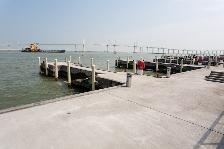
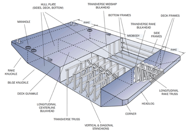
-

اسکله شمع و عرشه

اسکله­ شمع و عرشه (Suspended deck structures)

اسکله های شمع و عرشه تماماً با نمایی باز اجرا می­ شود به همین دلیل به آن اسکله باز (open-type) می­ گویند. این نمونه اسکله از انواع بسیار متعارف اسکله در بنادر خلیج فارس است. آب می­ تواند از زیر این سازه عبور کند، بنابراین می­ تواند در محل­ هایی که درمعرض جریان شدید آب قرار دارند مانند اسکله­ های کنار رودخانه­ ای مورد استفاده قرار گیرد. دراین سیستم نیروهای قائم توسط شمع ­هایی که درون بستر کوبیده می ­شوند بصورت اتکایی، اصطکاک جانبی و یا مجموعه آن­ها تحمل می­شوند. نیروهای جانبی به طرق مختلفی باربری می­ شوند. عمدتاً عرشه بتنی سازه، بارهای جانبی را در المان­ها توزیع می­ نماید.

اجزاء اسکله شمع و عرشه

در این نوع از اسکله هامعمولاً از شمع­های فولادی و بتنی پیش­ ساخته با مقاطع دایره­ ای یا مربعی استفاده می­شود. در این حالت شمع­ها تا عمق مناسب که پایداری و استحکام اسکله را تامین نماید کوبیده می­شوند. البته در بنادر کوچک(بنادر صیادی محلی) و بنادر قدیمی می توان شمع های چوبی را نیز مشاهده کرد که اگر از چوب مناسب و عمل آوری شده در ساخت آنها استفاده شده باشد، هنوز هم سالم و قابل بهره برداری هستند.

اسکله با شمع چوبی

یکی از مزایای اسکله های شمع و عرشه عملکرد خوب آنها در مناطق زلزله خیز است. و اگر در ساخت آنها از شمع های مایل جهت تامین باربری جانبی استفاده نشده باشد یا شمع های مایل با اتصال مفصلی اجرا شده باشند، می توانند زلزله های مختلفی را پشت سر بگذارند.

استفاده از شمع های مایل موجب می شود که سختی این اسکله ها در هنگام زلزله، در محل اتصال شمع مایل به شدت افزایش یابد و عرشه در آن ناحیه تخریب گردد که پس از آن نیز در بار گذاری های بعدی زلزله کاهش مقاومت در آن ناحیه موجب گسترش خرابی و از بین رفتن اسکله می شود. لذا اکیدا توصیه شده است که شمع های مایل در ساخت این اسکله ها به کار نرود و در صورت استفاده بصورت اتصال مفصلی استفاده شود.

اسکله بزرگ شمع و عرشه

اسکله های شمع و عرشه به نسبت سایر اسکله ها معمولا هزینه ساخت بالاتری را دارند و عملیات شمع کوبی بسیاری را تحمیل می کنند با این وجود در مناطقی که خاک بستر سست می باشد و باربری کافی را ندارد مجبور به استفاده از این نوع اسکله ها هستیم. استفاده از شمع های فولادی در این نوع اسکله ها نیازمند تمهیداتی مانند حفاظت کاتدیک مستمر و پوشش مناسب در ناحیه پاشش آب می باشد در غیر اینصورت با زنگ زدن و کاهش ضخامت شمع ها ظرفیت اسکله کاهش یافته و تخریب می گردد.

اجرای دال بتنی اسکله شمع و عرشه

اجرای تیر بتنی روی شمع

شمع های بتنی از لحاظ خوردگی مقاومت بیشتری را دارند و در صورتی که بصورت پیش ساخته و با رعایت نکات فنی در مورد جلوگیری از نفوذ یون کلر (حداقل سیمان ۳۵۰ تا ۴۰۰ کیلوگرم، نسبت آب به سیمان پایین، عمل آوری مناسب، استفاده از پوزولان در طرح اختلاط، مراقبت در برابر ترک به هنگام حمل و جابجایی و … ) تهیه شده باشند می توانند تا سال ها بدون نیاز به مراقبت مورد استفاده قرار گیرند.
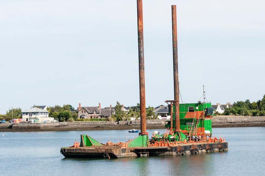
کوبش شمع در دریا

شمع های بتنی توخالی که به نام شمع های سانتریفیوزی نیز معروف هستند در ساخت اسکله های شمع و عرشه بکار می رود که دارای وزن مرده کمتر، مقاومت بیشتر در برابر خوردگی آب دریا، کوبش راحت تر می باشند و بخوبی نیز به یکدیگر متصل می شوند. البته در صورتی که در زمین های سخت بکار روند و یا با لایه سخت برخورد کنند کوبش آنها با چکش قوی موجب ایجاد ترک خواهد شد و به همین منظور باید در مراحل کوبش به این مساله دقت کرد.

2-5- روشهاي متداول اجراي اسكله هاي شمع و عرشه

اسكله ها و بطور كلي بنادر را به دو روش اصلي مي توان ساخت:

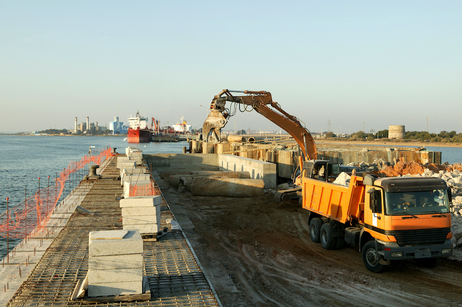
2-5-1- روش ساخت در دريا

در اين روش، سازه در محلي از دريا كه قبلاً مشخص شده است، در يك محيط كاملاً دريائي ساخته مي شود و اين روش از لحاظ تكنولوژي و مهارت نيروي انساني حائز اهميت است.

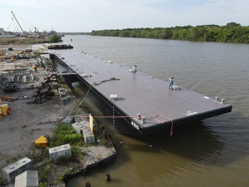
2-5-2- روش ساخت در خشكي

در اين روش كه در ايران متداول است، ابتدا تسهيلات بندري در خشكي ساخته شده و سپس در بندر آبگير مي شود. از نظر اقتصادي، در شرايط مختلف، هر كدام از دو روش مزبور ممكن است توجيه داشته باشد. دراين نوشته روش اول يعني ساخت در خشكي مورد نظر است از اينرو در ادامه جزئيات بيشتري از اين روش ارائه مي‌گردد. مراحل اجراي اسكله هاي شمع و عرشه در خشكي شامل مراحل زير است:

الف) عمليات خاكي

در اين مرحله، محل احداث اسكله تا عمق مورد نظر (كه معمولاً تراز لايروبي پاي اسكله است)، خاكبرداري شده و بستري مناسب (پلاتفرم) جهت استقرار دستگاه حفار تهيه مي گردد.

ب) حفاري محل شمعها

پس از تعيين محل دقيق شمعها به وسيله عمليات نقشه برداري، عمليات حفاري آغاز شده و شمع تا عمق مورد نظرحفاري مي شود. در اين شرائط به علت ريزشي بودن خاك، داخل چاه شمع با پنتونيت پر مي شود كه البته در خاكهاي بسيار سست كه امكان ريزش دهانه چاه در اثر استقرار دستگاه حفار در انتهاي حفاري وجود دارد، پيش از حفاري لوله هاي فولادي در ادبيات اجرائي تحت عنوان كيسينگ[5] خوانده مي‌شوند.

ج) آرماتورگذاري شمع

سبدآرماتوري كه قبلاً بافته و آمده‌شده است توسط جرثقيل و با اعمال رواداري‌هاي مجاز مكاني درون چاه شمع مستقر شده و در پايان اين مرحله، سبد آرماتور به صورت قائم و مستغرق در نبتونيت، درون چاه شمع قرار خواهد گرفت.

د) بتن ريزي شمعها

پس از استقرار ميلگردهاي شمع، در صورت مناسب بودن شرائط عمليات بتن ريزي كه عموماً با روش ترمي صورت مي گيرد، آغاز شده و با شروع بتن ريزي از انتهاي شمع، بنتونيت از شمع خارج و توسط دستگاهي ديگر مجدداً بازيافت و استفاده مي‌شود.

ه) قالب بندي ستون

با آمادگي و سطح مجاور شمع، بخش فوقاني شمع كه به ستون گفته مي شود قالب بندي شده و براي ادامه عمليات آماده مي شود.

و) آرماتورگذاري و بتن ريزي ستون

پس از آرماتورگذاري ستون، عمليات بتن ريزي انجام مي شود.

ز) اجراي تير كلاهك و عرشه

تير كلاهك[6] تيري است كه در پيشاني اسكله براي تامين سختي جانبي بيشتر و سطح مناسب جهت استقرار ضربه گيرها طراحي و ساخته مي شود. با رسيدن به تراز عرشه، تير مزبور و عرشه بتني اجرا مي شوند البته با توجه به سيستم عرشه (معمولاً دال ويتر)، اجراي دال مستلزم داربست بندي است. نظر به طول نسبتاً بلند ستونها و طرح مباحثي مانند كمانش، معمولاً طراحان ترجيح مي دهند كه در ترازي در حدود تراز حداقل جزر، از يك مجموعه تيرهاي سخت كننده استفاده نمايند. استفاده از اين تيرها، علاوه بر تامين سختي جانبي بيشتر، و كنترل طول كمانش ستونها، پايه اي مناسب را جهت استقرار داربست مربوط به قالب بندي و بتن ريزي عرشه مهيا مي‌كند.

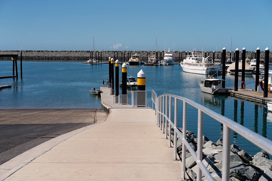
ح) اجراي راههاي دسترسي و آبگيري اسكله

راههاي دسترسي (پل دسترسي) به اسكله نيز داراي روند اجرائي مشابه با سازه اصلي بوده و پس از اتمام اجراي آن اسكله آماده آبگيري است. جهت آبگيري، اب دريا توسط پمپ به داخل حوضچه (كه قبلاً تراز لايروبي مورد نظر رسيده است)، منتقل شده و عمليات اجرا، با حذف سد موقت بين حوضچه و دريا و لايروبي ورودي حوضچه تا تراز مطلوب به پايان مي رسد.

3-1- مقدمه

در فصل حاضر نكات آئين نامه اي طراحي اسكله هاي شمع و عرشه ارائه گرديده و مباني ارائه شده در اين فصل بعنوان فرضيات طراحي اسكله و بارگذاري آن منظورشده است.

3-2- پارامترهاي مهم طراحي

اصلي ترين پارامترهاي طراحي يك اسكله عبارتند از:

3-2-1- ابعاد و ظرفيت كشتي ها

در شروع طرح يك اسكله، وزن و اندازه بزرگترين كشتي پهلوگيرنده بايستي مشخص گردد. اين پارامترها مبناي تمام طرحهاي بعدي خواهد بود.

از روي آبخور كشتي ها اندازه آبخور اسكله و از مقدار وزن و اندازه كشتي، طول و عرض اسكله مشخص مي شود. براي طراحي يك اسكله اطلاعات زير در رابطه با كشتي مورد نياز مي باشد:

الف) ظرفيت و ابعاد كشتي (بزرگترين كشتي) پهلوگيرنده، شامل طول و عرض و آبخور.

ب) تعداد كشتي هاي پهلوگيرنده.

ج) زمان تخليه و بارگيري كشتي ها.

د) ابعاد و وزن كالاهائي كه تخليه و يا بارگيري خواهند شد (براي طراحي تجهيزات تخليه و بارگيري).

3-2-2- نوع تخليه و بارگيري

اين عامل در اسكله يك مسئله اساسي مي باشد. در اسكله هاي نفتي و مايعات، از سيستم پمپ استفاده مي شود، بنابراين اين گونه اسكله ها مي تواند بصورت سبك ساخته شود. اسكله غلات و مواد معدني عمدتاً داراي تجهيزات تسمه نقاله براي تخليه و بارگيري مي باشند.

براي كالاهاي عمومي از جرثقيل ها استفاده مي شود كه داراي چهار نوع عمده زير است.:

الف) جرثقيل ثابت.

ب) جرثقيل متحرك روي ريل كه در طول كشتي حركت مي كند.

ج) جرثقيل تلسكوپي كه منطقه زيادي را پوشش مي دهد.

د) جرثقيل هاي شناور كه غالباً براي تخليه كشتي هاي پهلوگيرنده دور از ساحل بكار مي رود.

3-2-3- ظرفيت بندر

براي محاسبه تعداد اسكله لازم، طول لازم براي پهلوگيري كشتي ها و ظرفيت وسائل تخليه و بارگيري، داشتن ظرفيت سالانه بندر ضروري است. براي تعيين ظرفيت بندر بايستي كليه عمليات مربوط به پهلوگيري، مهاربندي، تخليه و بارگيري با زمانهاي مربوطه در نظر گرفته شوند. در اين روند، لازم است شرائط بد آب و هوائي، شرائط جزر و مدي و كلاً شرائطي را كه در انجام عمليات يك بندر وقفه ايجاد مي كند، مورد بررسي قرار گيرد.

3-2-4- موج طرح

آئين نامه ژاپن سرعت باد بحراني و ارتفاع موج بحراني در حوضچه را براي مصونيت كشتي ها در بندر به شرح جدول (3-2) معين كرده است (1991، مرجع 6).

جدول 3-2: سرعت باد و ارتفاع موج بحراني در شرائط مختلف

اندازه كشتي

مشخصات باد و موج

مهار به‌اسكله

لنگر اندازي

وضعيت بحراني براي ورود به بندر

1000-300 تن

سرعت باد (متر بر ثانيه)

20

30

25

ارتفاع موج (متر)

0و7

1

1.5

5000-1000 تن

سرعت باد (متر بر ثانيه)

20

30

20

ارتفاع موج (متر)

0و7

1.5

1.5

بيش از 5000 تن

سرعت باد (متر بر ثانيه)

20

30

15

ارتفاع موج (متر)

1

1.5

1.5

3-2-5- عمق لايروبي حوضچه و كانال دسترسي

براي محاسبه پي اسكله ها، مخصوصاً اسكله هاي وزني و سپري، مقدار عمق لايروبي داخل حوضچه و يا بي اسكله بسيار حائز اهميت است. در اسكله هاي سپري، معمولاً پاي اسكله بعد از تمام شدن سپر كوبي، لايروبي مي شود، در محاسبه عمق لايروبي عوامل زير موثرند:

الف) مقدار متوسط حداقلتراز جزر (M.L.L.W)

ب) حداكثر آبخور كشتي

ج) تركيبي از حركات مختلف كشتي (دوران حول محورهاي سه گانه كشتي)

د) فاصله اطمينان مورد قبول

ه) جنس بستر دريا

3-2-6- طول اسكله

طول اسكله بر مبناي تعداد كشتي هائي كه بطور همزمان در كنار اسكله پهلوگيرنده تعيين مي گردد. در طول اسكله نوع دو طول كشتي از عوامل تعيين كننده است. طول پهلوگير بايستي به اندازه طول كشتي بعلاوه فاصله مورد نياز بين كشتي ها به هنگام پهلوگيري و جداسازي از اسكله باشد. در طرح جامع بنادر ايران طولهر پهلوگير براي

ب: كشتي هاي باركش كوچكتر كنارهر دو اسكله با يك رديف قايقهاي باري و يك راه عبور با پهناي چهار برابر عرض كشتي هاي مذكور موجود باشد بطوريكه دو كشتي بتوانند از كنار هم عبور كنند.

ج: در بنادر رودخانه اي[7]، بايستي عرض راههاي آبي آنقدر باشد كه بتوان يك رديف ستون مهار بند در وسط معبر بعنوان لنگر گاه‌هائي جهت كشتي ها، قرار داد، تا اين گونه كشتي ها بتوانند بارشان را مستقيماً به قايقهاي باري و رودخانه پيما تخليه نمايند.

3-2-9- ارتفاع اسكله

ارتفاع اسكله با توجه به آبخور كشتي و تغييرات سطح آب بر اثر جزر و مد تعيين مي گردد. آئين نامه هاي مختلف براي ارتفاع اسكله، اعداد متفاوتي را پيشنهاد كرده‌اند. طرح جامع بنادر ايران، حداقل ارتفاع اسكله را براي كشتي هاي اقيانوس پيما برابر 20 متر بالاتر از متوسط مدهاي بزرگ (MHHW) يا 5/0 متر بالاتر از حداكثر مد (EHW) تعيين نموده است. اين ضابطه براي بنادر كوچك خليج فارس 1 متر بالاتر از (MHHW) و براي بنادر درياي خزر 5/2 متر بالاتر از متوسط سطح آب دريا (MSL) توصيه شده است. (1977، مرجع 7) شاپن ارتفاع كلي اسكله را از كف دريا، برابر مجموع حداكثر آبخور كشتي طرح و حداكثر تغييرات سطح آب به اضافه 2 تا 3 متر توصيه كرده است (1982، مرجع 1) آئين نامه كارهاي دريائي ژاپن در مورد ارتفاع اسكله هاي چسبيده به ساحل و يا ديوارهاي ساحلي اعداد جدول 3-5 را پيشنهاد نموده است. (1991، مرجع 6)

جدول 3-4: ارتفاع اسكله براي كشتيهاي مختلف

نوع اسكله

اختلاف جزر و مد

كمتر از 3 متر

بيشتر از 3 متر

اسكله براي كشتي هاي بزرگ (آبخور 5/4 متر يا بيشتر)

2/0-1/0 متر

5/1-5/0 متر

اسكله براي كشتي هاي كوچك (آبخور كمتر از 5/4 متر)

5/1-5/0 متر

0/1-3/0 متر

اين اعداد حداقل ارتفاع اسكله بالاتر از (MHHW) را نشان مي دهد. در هر صورت ارتفاع اسكله بايد به نحوي انتخاب شود كه موج به زير اسكله برخورد نكند.

3-3- بارگذاري اسكله هاي شمع و عرشه

3-3-1- بار مرده

بار مرده عبارت است از بارهائي كه مقدار آنها با توجه به نحوه بهره برداري و زمان تغيير نمي كند. بعضي از انواع اين بارها را مي توان بصورت زير بر شمرد:

الف) وزن سازه، شامل وزن كليه المانها مثل پايه ها، ديوارها، تيرها، دال ها و ساير اجزاء نصب شده در سازه‌. در طرح اوليه مي توان بار ناشي از وزن عرشه بتن مسلح را تقريباً برابر 9/1 تن بر متر مربع در نظر گرفت.

ب) وزن ماشين‌ آلات دائمي بر روي سازه مثل جرثقيل ثابت مستقر بر روي عرشه.

3-3-2- بار زنده

بارهاي زنده، بارهائي هستند كه با توجه به نحوه بهره برداري از سازه داراي مقادير مختلف بوده و در موقعيتهاي مختلف بر سازه اعمال مي گردد. با توجه به اين تعريف موارد زير را جزء بارهاي زنده مي توان بر شمرد:

الف) وزن وسايل و ماشين آلات مورد استفاده، كه داراي محل ثابتي نيستند نظير كاميونها و جرثقيل‌ها براي كاميون‌ها آئين نامه هاي مختلف، توصيه هائي ارائه نموده‌اند كه مثلاً براي بارگذاري كاميون طرح مي توان از ابلاغيه منفي شماره 11 وزارت راه و ترابري استفاده نمود (1994، مرجع 2). در مورد جرثقيل ها نيز مي توان مشخصاتي را كه توسط سازنده براي جرثقيل اعلام مي شود را مبنا قرار داد.

ب) وزن كالاهاي انباشته شده بر روي سازه

براي در نظر گرفتن بار ناشي از اين كالاها، در اكثر آئين نامه ها مرسوم است كه از سربار گسترده استفاده مي شود. اندازه اين بار گسترده در ارتباط مستقيم با نوع اسكله و بهره برداري از آن است. در طرح جامع بنادر ايران بارهاي گسترده براي موارد مختلف ارائه گرديده است. اين مقادير با توجه به نوع اسكله ساير مسائل 5/1 تا 5 تن بر مترمربع متغير است.

مثلاً براي اسكله هاي نفتي و سازه هاي مشابه كه مواد خام يا مواد فله را بوسيله لوله يا تسمه نقاله تخلين و بارگيري مي كنند بار زنده 5/1 تن بر مترمربع در نظر گرفته مي شود در اسكله هاي مورد استفاده براي جابجائي فلزات سنگين و اسكله‌هاي مورد استفاده كشتيهاي كانتيزبر، بار فوق حتي به مقدار 5 تن بر مترمربع هم بالغ مي‌شود. (1977، مرجع 7)

ج) نيروهاي وارد بر سازه در خلال استفاده از آن

ج-1) نيروي ناشي از پهلوگيري كشتي

در هنگام پهلوگيري كشتي، به سازه پهلوگير نيروهائي اعمال خواهد شد كه اين نيروها از اولين لحظه تماس تا هنگامي كه كشتي كاملاً مهار شود تداوم خواهد داشت، اندازه اين نيروها علاوه بر ابعاد كشتي طرح و سرعت پهلوگيري، به نوع و ضريب ارتجاعي ضربه گيرها نيز وابسته است. در حالتي كه خاكريزي در پشت اسكله هاي پهلوگيري استفاده شود، بارهاي افقي ناشي از ضربه توسط نيروي مقاوم[8] خاك پشت ديوار خنثي مي شود و به اين علت اينگونه اسكله در مقابل ضربه هاي افقي كمتر دچار شكست كلي مي شوند. در اسكله هاي ديوار ساحلي[9]، به علت محصور شدن آب بين بدنه كشتي و ديوار اسكله مقدار ضربه تا حدودي مستهلك خواهد شد. در محاسبه ميزان انرژي ناشي از پهلوگيري آئين نامه هاي مختلف روشهاي متفاوتي را ارائه كرده اند كه در ادامه روش آئين نامه ژاپن در اين خصوص تشريح مي گردد. (1991، مرجع 2)

ج-1-1) انرژي پهلوگيري

در اين روش پهلوگيري كشتي از رابطه زير قابل محاسبه است:

(3-1)

كه در اين رابطه:

:g شتاب ثقل

:W وزن جابجائي كشتي (tf)

:V سرعت برخورد كشتي در هنگام پهلوگيري و برخورد با ضربه گير (m/s) مولفه عمود بر سطح مد نظر است.

:Ce فاكتور خروج از مركز

:Cm فاكتور خروج مجازي

:Cs ضريب نرمي (براي حالت استاندارد برابر 1 مي باشد)

:Cc ضريب شكل پهلوگير (براي حالت استاندارد برابر 1 مي باشد)

در محاسبه انرژي پهلوگيري ذكر چند نكته حائز اهميت است:

الف) با توجه به رابطه نسبي بين وزن مرده (D.W) وزن جابجائي كشتي (D.T) روابط زير قابل استفاده اند:

(3-2)

(3-3)

در اين روابط

ب) ضريب نرمي Cs نسبت بين انرژي پهلوگيري و انرژي جذب شده بوسيله تغيير بدنه كشتي است. معمولاً انرژي جذب شده توسط بدنه كشتي كم بوده و از اينرو Cs=1.0 مورد استفاده قرار مي گيرد.

ج-1-2) سرعت برخورد كشتي

كشتيهاي مخصوص، نظير كشتي هاي مسافر بر و كشتي هاي كانتيز بر (كشتيهاي سيستم RO-RO) يا كشتيهاي كوچك مخصوص محل كالا، گاهي اوقات روشهاي پهلوگيري متفاوتي نسبت به كشتيهاي بزرگ بر مي گزينند مثلاً پهلوگيري را با استفاده از نيروي خود، بدون كمك يدك كش و يا با جابجائي موازي اسكله انجام مي دهند.

ج-1-3) فاكتور خروج از مركزيت

اين فاكتور از رابطه زير بدست مي آيد:

(3-4)

در رابطه قبل داريم:

:L فاصله اندازه گيري شده به موازات تجهيزات مهاربندي از نقطه تماس كشتي و اسكله تا مركز ثقل كشتي (m)

:r شعاع طولي چرخش كشتي (m)

رابطه (3-4) با ملاحظاتي نظير نحوه پهلوگيري توسط كاپيتان كشتي (مهارت وي)، مشخصات كشتي و نحوه قرارگيري ضربه گيرها بدست آمده است. در هنگام پهلوگيري به موازات محور طولي اسكله و در خلال عكس العمل ضربه گيرها، شناور شروع به چرخش[10] حول نقطه تماس نموده و نيز حول محور طولي خود هم دوران[11] مي كند (1989، مرجع 10)

در نتيجه بخشي از انرژي جنبشي مضمحل مي گردد اما استهلاك ناشي از چرخش حول نقطه تماس كمتر از دوران حول محور طولي بوده و قابل اغماض است. در تعيين رابطه فاكتور خروج از مركزيت، استهلاك ناشي از چرخش ملحوظ گرديده است. (1991، مرجع 6)

انواع درجه هاي آزادي براي يك جسم شناور

ج-1-4) فاكتور جرم مجازي

اين عامل از رابطه زير براي حالت استاندارد محاسبه مي گردد:

(3-5)

در اين رابطه:

:Cb ضريب بلوك

:d آبخور كشتي

:B پهناي كشتي (عرض موثر)

:L طول كشتي

: وزن مخصوص آب دريا

در استفاده از رابطه (3-5) نكات زير قابل توجه است:

الف) در زمان پهلوگيري كشتي هم جرم كشتي (Ms) و هم جرم آب اطراف كشتي در يك زمان تحت شتاب ناشي از ضربه واقع مي گردند. بنابراين نيروي اينرسي جرم آب بايد به جرم كشتي افزوده گردد. با توجه به مطالب مذكور ضريب جرم از رابطه زير قابل محاسبه اسن:

(3-6)

در رابطه قبل:

:Cm فاكتور جرم مجازي

:Ms جرم كشتي (جابجائي كشتي تقسيم بر شتاب جاذبه)

:Mw جرم افزوده اطراف كشتي

ب) معادله توسط يودا (Ueda) پيشنهاد شده است و اساس آن نتايج مشاهدات محلي و مدلهاي آزمايشگاهي است. (1991، مرجع 6)

ج-2) نيروي ناشي از مهاربندي كشتي

نيروي مهاربندي كه توسط كشتي به اسكله ها اعمال مي گردد ناشي از مهار كشتي به سازه مي باشد كه هم از طريق تماس بين كشتي و سازه و هم از طريق كشش در طنابهاي مهاربندي ايجاد مي گردد. اين نيرو در بنادر و محيطهاي حفاظت شده، اساساً ناشي از بادها و جريانهاي دريائي است كه هر دو بصورت جريانهاي آشفته، اعمال مي‌گردند. آئين نامه هاي گوناگون عمدتاً با توجه به وزن كشتي، حداكثر نيروي كششي ايجاد شده در مهاربند را به صورت نيروهاي متمركز تعيين مي كنند. آنچه در ادامه مي‌آيد روش آئين نامه ژاپن در تعيين نيروي مهاربندي كشتي هاست. (1991، مرجع6)

در تعيين اين نيرو موارد زير قابل طرح است:

الف) نيروي كششي بولاردها، با توجه به وزن كل كشتي در جدول (3-5) نشان داده شده است. در طراحي، فرض مي شود كه نيروي مذكور به صورت افقي و نصف همين مقدار به طور همزمان در جهت قائم اثر مي كند.

ب) نيروي كشش، در مورد كشتيهائي كه در جدول (3-5) ارائه نشده است، بايد با توجه به شرائط آب و هوائي و دريا و ساختار تسهيلات مهاربندي و اندازه گيري هاي مقدار كشش در محل تعيين گردد.

جدول (3-5) تعيين نيروي مهاربندي براي كشتيهاي مختلف

نيروي مهاربندها (تن)

وزن كل كشتي (تن)

15

500-200

25

1000-501

35

3000-1001

50

5000-3001

70

10000-5001

100

20000-10001

150

50000-20000

200

100000-50000

د) سربار ناشي از تغييرات سطح آب

بر اثر جزر و مد، سطح آب در ساعات مختلف تغيير نموده و اين تغييرات باعث ايجاد نيروي شناور مي گردد. تعيين نيرو به عنوان جزئي از بارهاي زنده در محاسبات اسكله ها حائز اهميت است. در خليج فارس و درياي عمان، آثار ناشي از تغييرات سطح آب زياد بوده و در طراحي بايد مد نظر قرار گيرد.

3-3-3- نيروي ناشي از تغيير شكل

اين نيروها كه بر اثر تغيير شكل به سازه اعمال مي گردد ممكن است در اثر تغييرات حرارت باشد كه مي تواند تنشهاي حرارتي در سازه ايجاد نمايد و يا اينكه ناشي از جابجائي خاك (اختلاف تست پي ها و تغيير مكان جانبي ديوار در اثر فشار خاك) و يا تغيير شكل سازه مجاور باشد.

3-3-4- نيروهاي ناشي از عوامل طبيعي

چه نيروهايي ناشي از پديده‌هاي طبيعي در حالت كلي از عوامل زير ناشي مي‌گردد؟

الف) نيروي ناشي از امواج

نيروي موج در موقعيت هاي مختلف و اشكال گوناگون سازه، اثرات متفاوتي بر جاي مي گذارد. رفتار موج در تعامل با سازه و با تعريف پارامتر بدون بعد كه در آن D قطر سازه و L طول موج است، در سه حالت بررسي مي شود:

(I) : در اين حالت موج از سازه تأثير ناچيزي پذيرفته و از تئوري اجسام كوچك[12] استفاده مي شود.

(II) : در اين حالت تئوري تفرق[13] حاكم خواهد بود.

(III) : در اين حالت مسئله انعكاس تعيين كننده بوده و لازم است كه از تئوري اجسام بزرگ[14] استفاده شود.

اسكله هاي شمع و عرشه در رده نخست قرار گرفته و به تعبير ديگر، چنين سازه‌هائي رژيم كلي جريان را چندان تغيير نمي دهند. در برآورد نيروي ناشي از موج روشهاي مختلفي وجود دارد كه از مرسوم ترين و در عين حال ساده ترين اين روشها، روش موسوم به روش موريسون (Morison) و نيز روش استاندارد آمريكا است كه در ادامه، به صورت مختصر به آنها پرداخته مي شود. (1989، مرجع 8)

برآيند نيروهاي رانشي را در حالت حداكثر بصورت زير مي توان نوشت:

(3-8)

(3-9)

در روابط قبل پارامترها عبارتند از:

:Fm حداكثر نيروي موج ناشي از مجموع نيروهاي اينرسي (FI) و نيروي رانشي (FD) كه در جهت موج بر روي سازه عمل مي كند.

:Mm لنگر حداكثر ناشي از مجموع نيروي اينرسي (MI) و رانشي (MD) كه نسبت به سطح بستر دريا تعيين مي شود.

:Qm ضريبي كه با مشخص بودن از شكلهاي (3-5) تا (3-7) تعيين مي گردد.

ضريبي كه با مشخص بودن از شكلهاي (3-8) تا (3-10) تعيين مي گردد.

W مطابق رابطه زير تعريف مي شود:

(3-10)

در محاسبه W، D قطر شمع و H ارتفاع موج است.

شكل

مقدار fDM از رابطه زير قابل محاسبه مي باشد.

(3-12)

نيروي حداكثر نيز مطابق رابطه زير تعريف مي شود.

(3-13)

كه در آن

(3-14)

مقدار Qm از اشكال (3-5) تا (3-7) بدست مي آيد.

:fm نيروي افقي وارد بر شمع در عمق Z مي باشد. با انتخاب مقادير مختلف براي Z مي توان نمودار توزيع نيروهاي افقي را بدست آورد.

كه انديس n بيانگر شماره شمع بوده و Ln و وي شكل مشخص شده اند. اگر فاصله شمعها به حد كافي زياد باشد، مي توان هر يك از شمعها را به صورت تنها در نظر گرفته و آناليز نمود به نحوي كه هر شمع روي ديگري اثري نخواهد داشت. در بخشهاي قبل در رابطه موريسون تغييرات نيروي موج، نسبت به زمان مشاهده شد. زاويه فاز را مي توان به صورت زير نشان داد كه در آن L طول موج و T پريود موج است.

روابط مربوط به نيروهاي اينرسي و رانشي، در محاسبه نيروهاي وارد بر يك شمع منفرد و با استفاده از تئوري موج خطي، به صورت زير خواهد بود.

(3-15)

(3-16)

روابط فوق براي يك شمع در موقعيت X=0 است و ممكن است به شكل كلي با جانشين كردن جديد بكار برده شود، يعني به جاي قرار داده شود.

با تشكيل جداولي، محاسبه كل نيروهاي افقي F(X) و لنگر حول سطح كف دريا، M(X) بعنوان تابعي از ارتفاع موج امكان پذير مي گردد. با انتخاب مبدا مختصات (شمع مبنا) در يك وضعيت جديد X=X2 نسبت به ارتفاع موج طرح، كل نيرو و لنگر وارد به گره شمع با روابط زير قابل محاسبه مي باشد.

(3-17)

(3-18)

5-1- مقدمه

در اين فصل ضمن جمع بندي كليه نتايج حاصل از تحليلهاي كامپيوتري و مطالب ارائه شده در فصول گذشته سعي شده است كه به يك نتيجه گيري مطلوب در بررسي رفتار انواع اسكله هاي شناور برسيم و در نهايت ضمنم ارزيابي نتايج حاصل از رفتار سنجي عمومي و رفتار سنجي تحت تركيبات بارگذاري و همچنين در نظر داشتن مسائل مربوط به جانمايي اعضاء مهاربند، محدوديتهاي كاربري و پايداري و… به نتيجه گيري كلي در انتخاب ابعاد بپردازيم.

5-2- ارزيابي عوامل موثر بر طراحي

1- بار زنده گسترده:

بار زنده گسترده كه براساس نوع كاربري اسكله مقادير متنوعي مي تواند داشته باشد در آرايشهاي خاصي مي تواند مشكل ساز باشد و طراحي ها را تحت تأثير قرار دهد مهمترين آرايش در يان خصوص بارگذاري نيم دهانه پانتون است كه در پانتون ابتدايي يك اسكله نتايج فرو رفت و شيب حداكثر قابل ملاحظه اي ايجاد مي كند.

2- بار زنده متمركز:

بار متمركز در نواحي گوشه هاي پانتونها به خصوص در پانتونهاي سر زنجيره نتايج قابل توجهي ايجاد مي كند. نتايج نشان داده است كه بار متمركز در سومين گوشه پانتون ابتدايي (مطابق شكل3-20) بحراني ترين نتايج فرو رفت و شيب طراحي را باعث مي گردد.

3- بار وسايل متحركم بر اسكله:

در اين خصوص پس از بررسي رفتار وانت، كاميون و جرثقيل بر اسكله هاي تعريف شده، ديده مي شود كه هر سه مورد متفقاً در شرايط واقع شدن در ابتداي پانتونها بخصوص پانتون اول، فرو رفت و شيب قابل ملاحظه اي ايجاد مي كند كه اين مطلب در مورد كاميون به دليل بزرگ بودن نسبي بار چرخها و نزديكي نسبي فواصل آنها بهم (نسبت به جرثقيل) از بقيه بحراني تر مي باشد.

4- نيروهاي وارد بر بولارد:

اين نيروها خطرسازترين نيرو از نظر پايداري اسكله هستند مولفه در راستاي قائم اين دسته نيروها كه در مورد اسكله هاي شناور در تقريباً همه موارد به صورت نيروي بالابر مي باشد در شرايط اثر بر ابتداي پانتونهاي درون زنجيره (بخصوص پانتون دوم) نتايج بسيار بحراني پديد مي آورد. اين بالا برندگي در برخي از موارد حتي منجر به جدا شدن بخشي از كف پانتونها از آب مي گردد كه در عمل استفاده از آن مدول را براي كاربري مورد نظر منتفي مي سازد. علاوه بر اين نيروي بالابر در پانتونهاي مجاور محل اثر خود باعث پيدايش شيبها و فرو رفت هاي بسيار شديد مي گردد كه گاهي بنا به محدوديتهاي كاربري منجر به رد يك مدول انتخابي مي شود. مولفه هاي عرضي و طولي اين دسته از نيروها نيز توسط عناصر نيروگير مهاري (شمع ها در اين حالت) تحمل مي شوند و تاثيري در فرو رفت و شيب اسكله نخواهند داشت و تنها در بحث‌هاي سازه اي و تعيين مدول مناسبي كه بتواند ضمن تحمل لنگرهاي حاصل در بدنه خود، قابليت انتقال اين نيروها به عناصر باربر جانبي را نيز داشته باشد مطرح خواهد شد.

اين نيروها علاوه بر تاثيرگذاري مستقيم بر سيستم سازه اي درون بدنه پانتون و گاهي ابعاد پانتون، تعيين كننده جانمايي و طراحي مقاومتي شمع هاي مهاري نيز هستند.

5- نيروهاي حاصل از پهلوگيري:

اين نيروها كه نيروهاي فندر ناميده مي شوند در عمل توسط عناصر باربر جانبي تحمل مي گردند نيروي وارد بر فندر بر فرو رفت و شيب اسكله تأثير چنداني ندارد و در عمل براي تعيين جانمايي و طراحي مقاومتي عناصر باربر جانبي و همچنين لنگرهاي وارد بر بدنه پانتون (كه در طراحي سازه اي بدنه كاربرد دارند) كاربرد خواهند داشت.

6- عوامل محيطي:

اصولاً اثرات باد و جريان در طراحي اسكله هاي شناور به طور ضمني در ارقام اتخاذ شده براي نيروهاي وارد بر بولارد و فندر لحاظ شده اند. اثرات موج نيز در اكثر موارد به دليل كوچكي در حوضچه احداث اسكله شناور، تأثير قابل توجهي بر طراحي آن ندارند.

5-3- ارزيابي رفتار عمومي اسكله هاي شناور تحت بارگذاري مختلف

چنانچه بخواهيم با مرور مطالب ارائه شده در فصل چهارم به يك جمع بندي كلي در مورد رفتار اين اسكله ها در مقابل بارهاي تعريف شده بپردازيم مي توان نتايج مهم زير را بر شمرد.

1- بار گسترده زنده به صورت كامل بر يك پانتون

الف) در بارگذاري كامل پانتونها، بارگذاري تعداد كمتري پانتون در سر زنجيره شرايط بحراني تر ايجاد مي كند. بارگذاري كامل پانتون اول بيشترين فرو رفت و شيب طولي را در اين حالت پديد مي آورد.

ب) افزايش طول پانتونها در حالت كلي در شرايط بارگذاري پانتونهاي سر زنجيره اثر كاهنده و در بارگذاري پانتونهاي ميان زنجيره اثر افزاينده اي بر فرو رفت دارد اما در مجموع همواره نتايج حاصل از فرو رفت پانتونهاي سر زنجيره مقادير بزرگتري دارند و نقش تعيين كننده خواهند داشت.

پس در مجموع مي توان با اين نگرش اعلام كرد كه افزايش طول پانتون در نهايت منجر به مقادير فرو رفت كمتري خواهد شد.

ج) افزايش طولي پانتونها در هر شرايطي از بارگذاري، كاهش شيب حداكثرطولي را در پي خواهد داشت.

د) افزايش طولتا حدي در بهبود شرايط فرو رفت و شيب حداكثر موثر خواهد بود و از طولهاي خاصي به بعد عملاً چندان موثر نخواهد بود.

2- بار گسترده زنده بر نيمي از سطح پانتون

الف) اين مدل بارگذاري به دو صورت نيمه راست و نيمه چپ قابل اجرا مي باشد و بارگذاري نيمه چپ به ويژه بر پانتون اول بيشترين فرو رفت و شيب حداكثر را در انواع حالت بارگذاري گسترده خواهد داشت.

ب) افزايش طول پانتون در شرايطي كه بارگذاري روي پانتون اول باشد بر مقدار فرو رفت تأثير چندان موثري ندارد ولي در پانتونهاي بارگذاري شده مياني باعث افزايش فرو رفت مي شود.

ج) افزايش طولي در هر شرايط بارگذاري در اين حالت، باعث كاهش شيب حداكثر خواهد شد.

د) شيب حداكثر حاصل از بارگذاري نيم دهانه بر پانتونهاي مياني با جابجا شدن محل پانتون بارگذاري شده عملاً تغيير محسوسي نمي كند.

3- بار گسترده زنده بر ربع سطح پانتون

الف) بارگذاري ربعهاي اول و سوم نسبت به دوم و چهارم ماكزيمم فرو رفت و شيب حداكثر بيشتري را پديد مي آورند كه اين مطلب در بارگذاري ربع سوم از پانتون اول بحراني ترين شرايط را مي دهد.

ب) افزايش طول پانتون در اين حالت بارگذاري اثر قابل توجهي بر ماكزيمم فرو رفت ندارد ولي باعث كاهش شيب حداكثر خواهد شد.

4- بار متمركز

الف) بار متمركز در گوشه سوم پانتونها نتايج بحراني تري مي دهد كه در مورد گوشه سوم پانتون اول اين نتايج به حداكثر خود مي رسند.

ب) اثر افزايش طول بر ماكزيمم فرو رفت به صورت يك رفتار ابتدا نزولي و سپس صعودي است به عبارت ديگر در طول خاصي (حدود 21 متر در مدول هاي انتخابي اين تحقيق) به مينيمم خود مي رسد.

ج) شيب حداكثر با افزايش طول پانتونها كاهش مي يابد.

5- وسايل نقليه متحرك و جرثقيل

الف) واقع شدن اين وسايل در ابتداي هر پانتون شرايط بحراني را پديد مي آورد كه اين مطلب بر پانتون اول بيشترين فرو رفت و شيب حداكثر را باعث خواهد شد.

ب) افزايش طول پانتونها باعث كاهش ماكزيمم فرو رفت و شيب حداكثر خواهد شد كه اين مطلب از طولهاي خاصي به بعد عملاً بي تأثير خواهد شد.

ج) افزايش طول پانتون در مورد بارگذاري چرخ جرثقيل سريعتر باعث كاهش ماكزيمم فرو رفت مي گردد و اين به دليل فاصله بيشتر محورهاي آن از هم مي باشد.

6- نيروي بولارد

اعمال مجموعه مولفه هاي اين نيرو در گره‌هاي اوليه پانتون دوم بحراني ترين شرايط را ايجاد مي كند كه دو تا سه پانتون مجاور خود را نيز تحت تأثير قرار مي‌دهد.

5-4- نحوه ارزيابي عملكرد اسكله هاي شناور در بارگذاري تركيبي

همانطور كه در بخش 4-5 ديده شد در مورد هر سه تيپ اسكله و با طول و عرض‌هاي مختلف مدولهاي انتخابي نتايج متفاوتي بدست مي آيد كه در جداول 4-1 تا 4-9 ارائه شده اند در اين حالت با توجه به نكات زير ارزيابي لازم در مورد هر گزينه را انجام مي دهيم:

الف) در مورد هر سه تيپ اسكله جدا شدن تماس پانتون با آب به منزله نامناسب بودن آن گزينه مي باشد.

ب) در اسكله هاي تيپ مسافري (تيپ اول) حداكثر شيب مجاز 5% و حداكثر فرو رفت به دليل ايجاد ايمني و‌ آسايش مسافران 50 سانتي متر اتخاذ مي گردد و گزينه‌هايي كه تامين كننده اين شروط نباشند مردود خواهند بود.

ج) در اسكله هاي تيپ دوم و سوم حداكثر شيب مجاز با توجه به عريض بودن پانتونها و ايمني لازم به ترتيب 6% و 7% اختيار مي شوند.

د) در مورد ماكزيمم فرو رفت مجاز در مورد اسكله هاي تيپ دوم و سوم محدوديتي قائل نمي شويم زيرا ارقام حاصل از بارگذاري تركيبي با اعمال آني همه بارهاي تعريف شده بدست مي آيند. اين در حالي است كه عملاً اين بارها طي زمان و به طور جداگانه اعمال مي شوند و با هم تركيب مي شوند. لذا فرو رفت كل حاصل از تحليل در عمل مجموع دو يا چند فرو رفت نسبي است كه پس از هر اعمال بار بوجود مي آيد و حتي بحراني ترين آنها يعني بولارد هم به تنهايي فرو رفتي در حدود مجاز تعريف شده در مراجع [5] كه معمولاً cm50 است خواهد داشت.

5-5- نتيجه گيري نهايي در مورد مدول مناسب

با توجه به نتايج فصلهاي سوم و چهارم اكنون به قضاوت نهايي در مورد مدولهاي مناسب هر تيپ اسكله خواهيم پرداخت.

5-5-1- اسكله تيپ اول (مسافري)

الف) عرض 3 متر

اين مدل از نظر تعداد تكيه گاههاي لازم براي عنصار باربر جانبي مشكل خاصي ندارد و با توجه به نتايج حاصل از بارگذاري تركيبي، استفاده از مدولهاي به طول 9 متر از نظر شيب مجاز دچار مشكل خواهد شد لذا استفاده از مدولهاي به طول 12 متر به بالا بلامانع مي باشند.

ب) عرض 4 متر

در اين مدل نيز تعداد تكيه گاهها محدوديتي ايجاد نمي كند مدول 9 متري از نظر شيب، اندكي از حد مجاز تجاوز مي كند. لذا مدولهاي 12 متر به بالا توصيه مي‌شوند.

ج) عرض5 متر

در اين مدل به دليل عريض بودن نسبي اسكله و كوچك بودن نسبي بارهاي وارد بر اسكله تيپ اول، هيچ محدوديتي نداشته و از كليه مدولهاي از 9 متر الي 60 متري مي توان استفاده كرد.

5-5-2- اسكله تيپ دوم (باربري سبك)

الف) عرض 5 متر

در اين مدل پانتونهاي با طول كوچكتر از 18 متر از نظر شيب مقادير بالاتر از حد مجاز خواهند داشت. از سويي بزرگ بودن نسبي نيروهاي جانبي وارد بر اسكله و بزرگ شدن ابعاد اعضاء نيروگير جانبي نيز براي پانتونهاي 9 و 12 و بخصوص 15 متري (به دليل نياز به سه تكيه گاه در طول خود) عامل محدود كننده اي است كه انتخاب آنها را مردود مي نمايد. لذا پانتونهاي 18 متر و بزرگتر پيشنهاد مي گردند.

ب) عرض 6 متر

در اين مدل نيز پانتونهاي با طول 18 متر و بيشتر شيبهاي مجايز خواهند داشت و محدوديت خاصي از نظر تعداد تكيه گاه نخواهند داشت.

ج) عرض 8 متر

در اين مدل نيز پانتونهاي با طول 18 متر و بزرگتر مجاز خواهند بود.

5-5-3- اسكله تيپ سوم (باربري نيمه سنگين)

الف) عرض 6 متر

در اين مدل به دليل بزرگي نيروهاي جانبي، بخصوص بولارد، محدوديتهاي زيادي ايجاد مي شود. مدولهاي 9، 12 و 15 متري به دليل نياز به سه تكيه گاه و قطور بودن نسبي تكيه گاهها و ايجاد فاصله آزاد اندك بين تكيه گاهها از نظر اجرايي و تأثير رفتاري شمعها (يا گروه شمعها) بر هم مناسب نيستند. پانتونهاي 18 و 21 متري نيز كه نياز به چهار تكيه گاه دارند تقريباً همين مشكل را دارند.

از سوي ديگر پانتونهاي تا طول 30 متر تحت اثر مولفه بالابر نيروي بولارد در تركيب بارگذاري بحراني ارائه شده، در نقاطي از وجوه در تماس خود با آب از آب جدا مي شوند و عملاً مردود خواهند بود. لذا از اين گروه فقط پانتونهاي 45 و 60 متري مقبول خواهند بود كه از نظر شيب حداكثر هم مشكلي ندارند.

ب) عرض 7 متر

در اين مدل پانتونهاي با طول 18 متر و بيشتر از آب جدا نمي شوند و مناسب خواهند بود اما از نظر شيب حداكثر مجاز و تعداد تكيه گاههاي لازم در عمل پانتون‌هاي با طول 24 متر به بالا مناسب خواهند بود.

ج) عرض 8 متر

در اين مدل نيز پانتونهاي با طول 18 متر و بيشتر از آب جدا نمي شوند ولي در عمل با توجه به شيب حداكثر مجاز و تعداد تكيه گاههاي لازم، پانتونهاي با طول 24 متر به بالا مناسب خواهند بود.

نتايج حاصل را مي توان در قالب جدول 5-1 ارائه كرد:

جدول 5-1: طول پيشنهادي پانتونها براي هر تيپ اسكله

5-5-4- تعيين ارتفاع مناسب براي هر مدول

براي اين منظور با توجه به اصول پايداري ارائه شده در فصل سوم و نتايج فرو رفت حاصل در فصل چهارم، ارتفاع مناسب هر تيپ اسكله را در عرضهاي مختلف مي‌پاييم.

به عنوان مثال براي اسكله تيپ اول با عرض 3 متر با اتخاذ نسبت پايدار (كه در بخش 3-2 ارائه شد) خواهيم داشت:

از طرفي ماكزيمم فرو رفت بدست آمده در تحليل اين مدول حدود 80 سانتي‌متر ‌مي‌باشد. لذا با فرض ارتفاع آزاد حدود 20 سانتي‌متر مي توان h=1m را پيشنهاد داد. ساير نتايج بهمين ترتيب محاسبه و در جدول 5-2 ارائه شده اند.

جدول 5-2: ارتفاع پانتونها در تيپهاي مختلف

5-6- نتيجه گيري كلي

1- بارهاي موثر بر اسكله هاي شناور متنوع بوده و هر يك به گونه اي مي توانند شرايط بحراني را در طراحي ايجاد كنند كه الگوي تاثيرگذاري هر يك از اين بارها در اين تحقيق به طور كلي ارزيابي گرديد.

2- عرض مناسب براي هر نوع اسكله براساس نوع كاربري تعيين شد.

3- با داشتن نيروهاي جانبي وارد بر اسكله و در نظر گرفتن مقاومت قابل تحمل سيستم سازه‌اي بدنه مي توان صرفنظر از مسائل مربوط به طراحي عناصر نيرو بر جانبي تعداد و موقعيت آنها را نسبت به هم پيش بيني كرد.

4- با اتخاذ يك سري بارهاي الگو براي سه تيپ اسكله تعريف شده و ايجاد تركيبات تعيين كننده مي توان با تحليل كامپيوتري حداقل طولهاي لازم براي پانتونهاي هر نوع اسكله با عرضهاي متفاوت را يافت.

5- ارتفاع پانتون در هر حالت براساس ماكزيمم فرو رفت مشاهده شده در نتايج حاصل از تحليل تحت تركيبهاي بارگذاري، در نظر گرفتن يك ارتفاع آزاد و تامين حداقل ارتفاع لازم براي پايداري بدست مي آيد.

2-3-1- شمعهاي چوبي

شمعهاي چوبي قديمي ترين نوع شمع هستند كه هنوز هم به طور بسيار محدود استفاده مي شود. سابقاً براي حفاظت شمع از حملات دريايي، چوب را با پوست در زمين مي كوبيدند. اما امروزه شمعها چوبي را با كروزوت يا آرسنات كرومات مس اصلاح مي كنند. بعضي چوبها به طور طبيعي در مقابل حملات دريايي مقاوم هستند. اما به هر حال تمام چوبها بايد براي پوسيدگي در مقابل آب دريا حفاظت شوند.

باربري معمولي اين شمعها 15 تا 20 تن مي باشد ولي تا 30 تن هم مي توان اين ظرفيت را بالا برد. طول متداول شمعهاي چوبي حدوداً 15 تا 20 متر مي باشد كه در شرايط استثنايي تا طول 35 متر نيز قابل اجراست. حالت باريك شونده شمع چوبي و ضريب اصطكاك منطقي بين خاك و چوب، اين شمعها را براي باربري اصطكاكي مناسب مي كند. البته اين شكل باريك شونده در شرايط نيروهاي كششي از ظرفيت شمع مي كاهد. ظرفيت نوك شمع نيز گاهي قابل توجه مي باشد به خصوص وقتي كه سطح نوك شمع بزرگ باشد. اما چنانچه روي باربري نوك شمع حساب شود، لازم است طراح به شكستن چوب و ترك خوردگي آن نيز توجه كند.

2-3-2- شمع بتني لوله اي و توپر

شمعهاي بتني پيش تنيده، كه امروزه از رايج ترين شمعهاي پر ظرفيت مي باشد مي‌تواند با شكل، قطر و طولهاي مختلف توليد شود. پيش تنيدگي سبب مي شود شمع قابليت بيشتري در تحمل خمش و تنش هاي كششي ناشي از وزن شمع در هنگام حمل، از خود نشان دهد.

هر چند شمعهاي بتني پيش تنيده، بيشتر براي باربري جداره ساخته مي شوند، اما مي‌توان روي باربري نوك آنها نيز حساب كرد. ظرفيت اين شمعها بيشتر از 120 تن است و طول آنها نيز معمولاً بيش از 35 متر مي باشد.

به منظور جلوگيري از خرابي نوك اين شمعها، معمولاً يك ورق فولادي در نوك آن كوبيده مي شود. در خاكهاي سفت از يك قطعه -H شكل فولادي در نوك شمع استفاده مي شود.

لوله هاي بتني پيش تنيده نيز در مواردي كه نيروهاي قائم و افقي زيادي به سازه وارد مي شود. مورد استفاده قرار مي گيرد. مزيت استفاده از شمعهاي لوله اي در ظرفيت خمشي بيشتر آنها نسبت به ظرفيت شمعهاي توپر با وزن مساوي مي باشد. اين شمعها را مي توان بصورت صندوقه نيز در خاكهاي خوب مورد استفاده قرار داد.

مهندسين طراح بايد در تعيين طول شمع بتني، دقت زيادي نمايند. هرچند روشهاي مختلفي در اتصال قطعات اين شمعها به همديگر وجود دارد.


[1] . off-shore

[2] . on-shore

[3] . Suspended-Deck Structures

[4] . Open-Type Structures

[5] . Casing

[6] . Cap Beam

[7] . River Harbour

[8] . Passive

[9] . Quay Wall

[10] . Yawing

[11] . Rolling

[12] . Small Body

[13] . Diffraction

[14] . Larg Body

مشاور سازه های دریایی و معادن و لایروبی و موج شکن

به قول برخی بزرگان ، هدف خودت تعیین کن و به سمتش حرکت کن ، ممکن برای رسیدن به اهدافت چالشهای بسیاری را ببینی و در نهایت با حضور چالشها همچنان با تمرکز به اهداف خودت حرکت کن ، پله پله به اهدافت خواهی رسید ، هیچ موفقیت یک شبه به دست نمیاد ، پس ناامید نشو و دستانت را به خداوند بزرگ بده و به سمت اهدافت حرکت کن .

از مسیر زندگیت لذت ببر .

توضیح عکس ذیل :

عکس بالا مربوط به پروژه بندر خدماتی وصادراتی تمبک در عسلویه و عکس پایین مربوط به بندر شیلاتی اطراف بندر لنگه می باشد ، که افتخار حضور اینجانب به خواست خداوند ، در پروژه تمبک حضور داشتم و در پروژه بندر شیلاتی حضور دارم .

دوستدار همگیتان و آرزوی بهترین ها برای همگان از خداوند متعال

مشاور سازه های دریایی و معادن

حقیقتاً توصیه اکید من این هست که با توکل به خدا به سمت جلو حرکت کنید ، انسانی که مصمم هست هیچ مانعی نمی تواند جلو دارش باشد ، خودتان را به خداوند بزرگ بسپارید ، راه درست را نشانتان می دهد .

دو عکس از دوبندر متفاوت ، بالا بندر خدماتی و صادراتی تمبک که بنده افتخار حضور در آن پروژه را داشتم و عکس پایین مربوط به بندر نزدیکی بندر لنگه می باشد .

دستانم در دست خداوند هست و خیلی دوستانه بگم ، ولش نمی کنم .

دوستدار همگی شما

#خدا #god #breakwater #engineer #مهندسین مشاور